background image

MarkLED 4


Page 9 / 38 

Created 

03.10.2017 

chal 

Modified 

28.11.2017 

chal 

Object-ID 

850593 

1. 

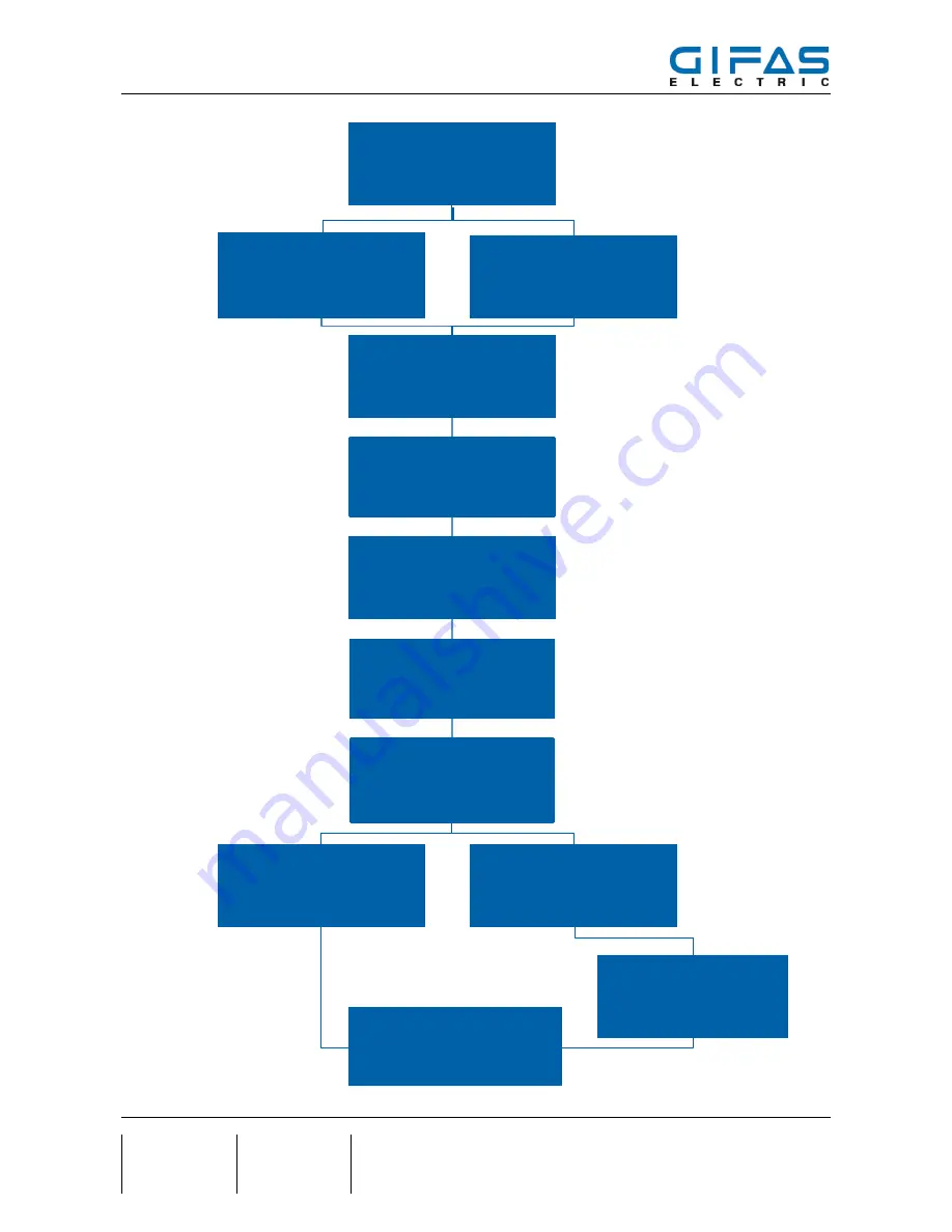
Measure and mark 

2a. 

Milling a groove in the 

shoulder 

2b. 

Remove bitumen from 

groove / remove old system 

3. 

Rework of groove for cur-

rent collector 

4. 

Inserting the connecting 

cables 

5. 

Mount current collector onto 

system cable 

6. 

Install current collector in 

groove 

7. 

Put on the MarkLED 

8a. 

Seal groove 

8b. 

Insert system profile 

10. 

Installation of the control unit 

including parameterisation 

9. 

Seal MarkLED 

4  Process 

Summary of Contents for MarkLED 4

Page 1: ...MarkLED 4 Page 1 38 Created 03 10 2017 chal Modified 28 11 2017 chal Object ID 850593 MarkLED 4 Installation instructions VERSION MODIFICATIONS 1 0 First edition ...

Page 2: ...ontraflow 11 7 Measuring of MarkLED placement with current collector 12 8 System cable and current collector 13 8 1 Milling a groove in the shoulder 13 8 2 Remove bitumen from groove remove old system 14 8 3 Create mounting and current collector bores 15 8 4 Inserting connecting cables 16 8 5 Mount current collector onto system cable 17 8 6 Install current collector in groove 18 8 7 Seal the groov...

Page 3: ...paration of cables conductors 27 9 7 3 Connection MarkLED light module 27 10 Installation MarkLED surface mounted box 29 10 1 Attachment 29 10 2 Installation 29 10 3 Connection 30 10 4 Sealing compound 30 11 Installation of MarkLED recess mounted adapter in formwork 31 11 1 Mark drill and fasten 31 11 1 1 Alternative attachment with 4 screws 31 11 2 Mount installation conduit 32 11 3 Remove formwo...

Page 4: ...MarkLED 4 Page 4 38 Created 03 10 2017 chal Modified 28 11 2017 chal Object ID 850593 14 Service 38 14 1 Service addresses 38 14 2 Imprint 38 ...

Page 5: ... intactness of the product and or could constitute a source of danger The manufacturer rejects any liability for damage which has been caused by incorrect or non intended use of the product In countries which do not belong to the European Community the national legal reference regulations as well as the standards and regulations applicable in these countries have to be observed for warranty of a c...

Page 6: ...ion conditions product MarkLED 4 The system installation of MarkLED also depends on a professional installation Improper work Extensive warranty work due to improper works We instruct you on each project site for the correct assembly so that a proper function of the system MarkLED can be ensured The cable cross section of the cable length must be adjusted to maintain the required operating voltage...

Page 7: ...f cables Light barping pliers for system cables 2x2 5mm Hot air gun Compressed air for cleaning the groove and the bores Hand press for 310ml cartridges In order to ensure the correct polarity and thereby the function as early as the installation stage we recommend using a supply volt age of 24VDC when connecting to the connection cables if neces sary a 24V battery can also be used ...

Page 8: ...ling profile item no 172211 loan material GIFAS 3 3 Consumables Heat shrink tube with glue 6mm 2mm item no 010300 insulation tape 2 M Scotch no 23 black item no 152743 crimp connector 1 5 2 5 hot shrinking Raychem blue item no 019875 Solder connector 1 5 2 5 heat shrinkable NSPA transparent item no 172745 Device for unrolling cables Cable lug crimping pliers for press connector Head lamp measuring...

Page 9: ...ove bitumen from groove remove old system 3 Rework of groove for cur rent collector 4 Inserting the connecting cables 5 Mount current collector onto system cable 6 Install current collector in groove 7 Put on the MarkLED 8a Seal groove 8b Insert system profile 10 Installation of the control unit including parameterisation 9 Seal MarkLED 4 Process ...

Page 10: ...MarkLED 4 Page 10 38 Created 03 10 2017 chal Modified 28 11 2017 chal Object ID 850593 5 Installation Example Adaption area 12 5m Rest 25m ...

Page 11: ...3 6 Electric power supply of the unit 6 1 Two tubes without adaption zone in the opposite direction 6 2 Two tubes with adaption zone in the opposite direction 6 3 A tube with contraflow Key Entry and crossover route Entry and crossover route in the opposite direction LED guidance system ...

Page 12: ... in accordance with project default by spray colour Recommendation Tunnel entrance adaption a MarkLED each 12 5 m according to ASTRA BAST regula tions Middle of tunnel a MarkLED each 25 m Tunnel exit adaption a MarkLED each 12 5 m according to ASTRA BAST regulations Colour markings Hint Due to obstacles pit joints etc the location of MarkLED has to be replaced as less as possible ...

Page 13: ...e shoulder Milling of a continuous groove width 6 mm depth 30 mm Distance between groove and roadway edge project specifically Milling around obstacles pits etc after project default Breite 6mm 1 0 Hint The system MarkLED makes a very small distance to the roadway edge possible depth 30mm 5 0 distance to the roadway edge roadway edge width 6mm 1 5 0 ...

Page 14: ...8 2 Remove bitumen from groove remove old system Machine scratch out of existing wiring 2 operations Suction and blowing out of the groove width 6mm 1 5 0 depth 30mm 5 0 distance to the roadway edge roadway edge Hint Waste has to be recycled in ac cordance with local national regu lations ...

Page 15: ... in the groove direction until it is centred on the previously marked light position Stand with both feet on the drilling jig and first drill bore ø40 mm depth 40 5 0 mm Make sure that the drilling jig stays in place and then drill a bore ø10 mm depth 25 5 0 mm Tolerances are to be kept in the depth 5 0 mm Then clean the entire groove and clean and dry all bores Durchgehend 6mm breit Länge 90mm co...

Page 16: ...from control unit according to project specifications observe channels lines Feed in 24V voltage Hint System MarkLED only needs a very small cross section due to the small power input Even with consideration of the voltage drop the cross section of 2 5 mm2 is sufficient Hazard Protect the cables against me chanical damage embedding in the cleaned groove system cable 2 5 mm2 particularly heat proof...

Page 17: ...shrink tubing with adhesive tightly over it Finally insert the sealed cable end into the groove and cast with liquid hot bitumen Hint The function check can be carried out simultaneously when connecting the MarkLED by having a 24VDC tension on the system cable It must be ensured that the screws are tightened with suitable tools M 1Nm Hazard No other installation materials may be used Hint By screw...

Page 18: ...collector in groove Installation location must be dry and clean before installing MarkLED current collector Hint Small unevenness approx 1 mm can be absorbed by using adhesives and sticking compound Apply Permafix to bottom of current collector Insert MarkLED into bores and press down weigh down if necessary ...

Page 19: ...oove either with sealing compound or joint profile according to the owner s stipulations Pre treat groove if necessary with primer Seal the groove with filler hot bitumen or epoxy glue do not use cold bitumen primer sealing compound according to stipulation Hazard An electrical function check must be performed before sealing ...

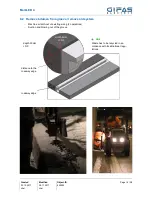
Page 20: ...a self tapping joint profile can be inserted over the system ca ble Leave 5 cm free both in front of and behind the MarkLED Fix profile every 5m with Permafix in the groove and before after every MarkLED Hazard Always seal the groove in the passable area 8 8 1 Installation with roll off and profile laying car hire material self tapping joint profile ...

Page 21: ...D 4 Page 21 38 Created 03 10 2017 chal Modified 28 11 2017 chal Object ID 850593 Install joint profile at a distance of approx 5cm from the MarkLED The area of the MarkLED must be cast with liquid hot bitumen ...

Page 22: ...onnect power supply unit Up to 4 lines connectable Program the unit s Hint The assembly of the control unit is to be implemented preferably before the shoulder assembly for the rea son that the operability control can take place within the placement The control unit and the associated power pack are preferably integrated into existing cabinets The space requirement is relatively small Control unit...

Page 23: ... mark the course of the groove through centres of the bores 9 1 1 Mill groove Mill groove using a floor saw with the appropriate cutting width Mill groove over a small distance check width and depth and correct if required Finish milling groove Depth 55mm 5mm Width 21mm for the installation conduit M21 2 9 1 2 Drill core holes Drilling core hole with diameter 140mm 10 0mm and depth 60mm 5 0mm Brea...

Page 24: ...sert into the hose connections 9 4 Place levelling jig Place levelling jig on recess mounted adapter and tighten central cylinder with hexagon screw Align flat profiles of the levelling jig approximately parallel to the cable slot 9 5 Set recess mounted box Approx required quantity of mortar for a recess mounted adapter 0 24dl water to 2dl CTW HR mortar equivalent to about 440g First add the water...

Page 25: ... flush on floor Press installation conduit down into groove on both sides Adapter should only go about 1cm in the mortar Hint Weigh down cemented adapter for flush mounting with weight if necessary 9 5 3 Remove levelling jig After approx 30 minutes of the mortar drying unscrew the levelling jig and place the blind chart to prevent it from get ting dirty The blind chart protects the recess mounted ...

Page 26: ...850593 9 6 Close groove 9 6 1 Close groove with mortar Press installation conduit into dust free and dry groove and seal flush or cover with mortar 9 6 2 Close groove with hot bitumen Press installation conduit into dust free and dry groove and seal flush or cover with hot bitumen ...

Page 27: ...of cables conductors Cut the cable loop and cut both cable lengths to 15 cm from hose connection Then strip both cables up to approx 5cm on the hose con nection 9 7 3 Connection MarkLED light module Coat seal ring sealing with silicone grease Position the seal ring on one side of the recess mounted adapter slightly overstretch it and slide it over the sealing surface on the opposite side Check if ...

Page 28: ...MarkLED 4 Page 28 38 Created 03 10 2017 chal Modified 28 11 2017 chal Object ID 850593 Strip cable conductors and the MarkLED to 11mm and con nect to the WAGO connection terminals item no 162224 ...

Page 29: ...The small seal ring should already be fitted and greased on the MarkLED Place seal ring on surface mounted housing We recommend using the following product for lubricating item no 017458 One unit can be used for hundreds of lamps Place seal ring on surface mounted housing Clean recess mounted adapter inside and dry Surface mounted adapter must be completely dry on the inside To check the installat...

Page 30: ... tubes so that they are not blocked by the compound e g Bluegel Item no 166534 1l container Hint To ensure a tight installation the contact surfaces of the surface mounted adapter must be absolutely clean Hint Make sure that the conductors are not pinched Place and align MarkLED on the surface mounted housing Press MarkLED on recess mounted housing by hand using lateral pressure and maintain press...

Page 31: ...n the formwork Length of M5 screw 15mm formwork thickness Put sealing ring item no Set 154914 onto recess mounted adapter Screw the recess mounted adapter to the back of the formwork with the previously inserted M5 screw Deter mine alignment of hose connections 11 1 1 Alternative attachment with 4 screws The MarkLED recess mounted adapter can alternatively be screwed onto the formwork from the bac...

Page 32: ...k Apply all installation conduit connections between the re cess mounted adapters 11 3 Remove formwork After the concrete has hardened the M5 fixing screw in the centre of the recess mounted adapter must be unscrewed before stripping Then stripping may begin Remove the sealing rings after stripping 11 4 Connection and installation of MarkLED For connection and installation proceed as described fro...

Page 33: ...power cable The underground must be flat and dry to ensure a solid and long lasting installation 12 2 Attachment We recommend the use of the following product for gluing MarkLED Hybrid adhesive and sealant Permafix 153 grey item no 020157 Depending on the condition porosity of the substrate a 290ml cartridge will suffice for approx 30 MarkLED s Only use water to clean MarkLED without any chemical ...

Page 34: ...ecause the orientation can only be adjusted minimally 12 3 1 Dimensions for drilling holes 12 4 Installation and connection of MarkLED Blow out drilling dust and clean the surface as dust free as possible for gluing the MarkLED Lead the connection cable of the MarkLED through the ca ble drilling Connect cable to junction box or cable sleeve Insert nylon dowels into the mounting bore Apply Permafix...

Page 35: ...ersunk screw 4 5x50 item no 17473 onto the ground M 2 5Nm Hint Never tighten the MarkLED mounting screws too tightly This could lead to the MarkLED failing in later operation due to stress cracks 12 5 Function check Energise feed in cable for function check GIFAS recom mends putting the feed in cable under 24V voltage at the beginning of the installation so that any failures can be de tected prior...

Page 36: ...ified 28 11 2017 chal Object ID 850593 12 6 Drilling jig Hint We recommend using the following drilling jig for precise drilling of the two holes It can be cut out and used on site for an exact determination of the drilling holes Direction of traffic ...

Page 37: ...MarkLED 4 Page 37 38 Created 03 10 2017 chal Modified 28 11 2017 chal Object ID 850593 13 Declaration of conformity ...

Page 38: ...24 Rheineck 49 2137 105 0 39 58 497 82 11 43 6225 7191 0 41 71 886 44 44 49 2137 105 230 39 58 493 99 24 43 6225 7191 561 41 71 886 44 49 www gifas de www gifas it www gifas at www gifas ch verkauf gifas de info gifas it verkauf gifas at info gifas ch 14 2 Imprint GIFAS ELECTRIC GmbH CH 9424 Rheineck www gifas ch Technical changes and errors reserved These installation instructions are the propert...

Reviews: