- 32 -
Hardware Installation
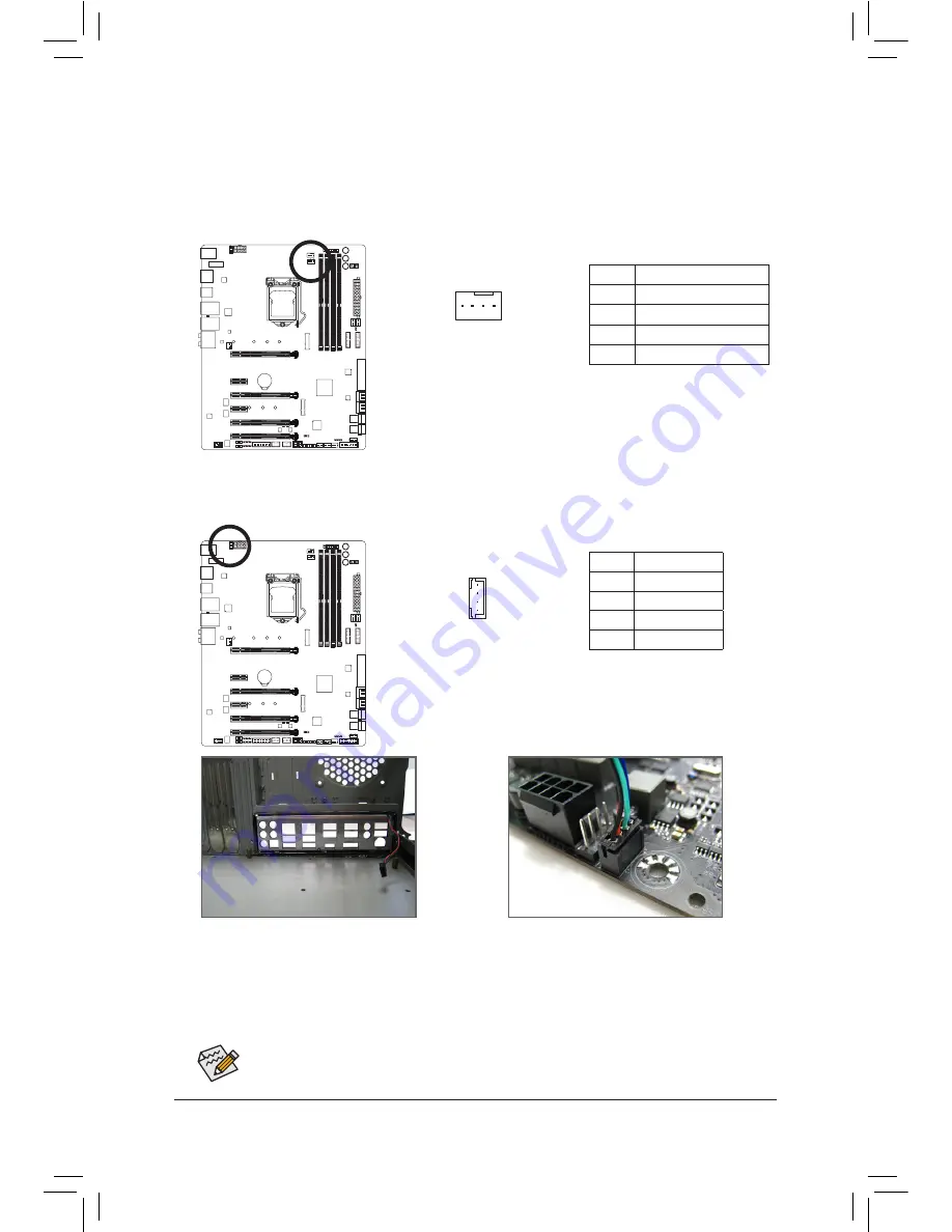
6) CPU_OPT (Water Cooling CPU Fan Header)
The fan header is 4-pin and possesses a foolproof insertion design. Most fan headers possess a foolproof
insertion design. When connecting a fan cable, be sure to connect it in the correct orientation (the black
connector wire is the ground wire). The speed control function requires the use of a fan with fan speed
control design.
DEBUG
PORT
G.QBOFM
1
7) LED_IO (I/O Shield Audio LED Power Connector)
The power connector provides power to the LEDs on the I/O shield on the motherboard back panel.
1
F_USB30
F_U
B_
F_
F_
_
B
BS_
B
SB_
B
_
S
S_
_
B
_U
_
B
S
12
3
1 2 3
12
3
12
3
1
1
1
1
BS
S
S
_S
S
S
U
1 2 3 4 5
S
3
BS
S
S
U
_
_
3
F_USB3F
S
_
S
_
S
_
S
F
B_
B_
F
_0
S
S
_0
F
_F
_
_
_
_B
U
S
_S
_
USB0_
B
B_
Pin No.
Definition
1
+5V
2
Red
3
Green
4
Blue
Pin No.
Definition
1
GND
2
Voltage Speed Control
3
Sense
4
PWM Speed Control
Step 1:
Install the included I/O shield into the chassis. (For
actual installation, please refer to the user guide
for your chassis.)
Step 2:
Place the motherboard into the chassis, aligning
the back panel connectors with the installed I/O
shield. Connect the power cable from the I/O shield
to the LED_IO connector on the motherboard.
For how to turn on/off the I/O shield LED indicators, refer to the instructions on in Chapter 2, "BIOS
Setup," "Peripherals," or Chapter 5, "Unique Features," "APP Center\RGB Fusion."
Summary of Contents for GA-Z270X-Gaming 8
Page 8: ... 8 ...
Page 86: ...Configuring a RAID Set 86 ...
Page 141: ... 141 Appendix ...
Page 142: ...Appendix 142 ...


