Hardware Installation
- 12 -
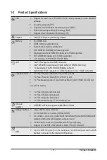
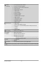
Internal
Connectors
1 x 24-pin ATX main power connector
2 x 8-pin ATX 12V power connector
2 x Mini-SAS connectors (SATA3 6Gb/s signal)
8 x SAS connectors
2 x SATA3 6Gb/s connectors
1 x PMBus header
2 x CPU fan headers
5 x System fan headers
1 x Front panel header
1 x HDD Back plane borad header
1 x USB 3.0 header
1 x TPM module connector
1 x Serial port connector
2 x SAS SPGIO headers
1 x IPMB connector
Rear Panel I/O
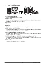
6 x USB 3.0 ports
1 x QSPF LAN port (MD60-SC0 Only)
3 x RJ-45 ports (1 x 10/100/1000 Mbps dedicated management LAN port)
1 x COM port
1 x VGA port
1 x PS/2 connector
I/O Controller
ASPEED
®
AST2400 BMC chip
Hardware
Monitor
System voltage detection
CPU/System temperature detection
CPU/System fan speed detection
CPU/System fan speed control
* Whether the CPU/system fan speed control function is supported will depend on
the CPU/system cooler you install.
BIOS
1 x 128 Mbit flash
AMI BIOS
Form Factor
EATX Form Factor; 12.9 inch x 12 inch, 8 layers PCB
* GIGABYTE reserves the right to make any changes to the product specifications and product-related information without
prior notice.
Summary of Contents for MD60-SC0
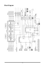
Page 9: ... 9 Block Diagram ...
Page 46: ...BIOS Setup 46 2 2 1 Serial Port Console Redirection ...
Page 47: ... 47 BIOS Setup ...
Page 61: ... 61 BIOS Setup 2 9 SIO Configuration ...
Page 62: ...BIOS Setup 62 ...
Page 67: ... 67 BIOS Setup 2 3 1 Processor Configuration ...
Page 70: ...BIOS Setup 70 2 3 1 1 Pre Socket Configuration ...
Page 77: ... 77 BIOS Setup 2 3 4 QPI Configuration ...
Page 81: ... 81 BIOS Setup 2 3 5 1 Memory Topology ...
Page 90: ...BIOS Setup 90 2 3 7 2 PCH sSATA Configuration ...
Page 95: ... 95 BIOS Setup 2 3 7 3 PCH SATA Configuration ...


