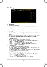
background image

2-6 Settings


ƒ

Platform Power


&

Platform Power Management


Enables or disables the Active State Power Management function (ASPM).  (Default: Disabled)


&

PEG ASPM


Allows you to configure the ASPM mode for the device connected to the CPU PEG bus. This item is 

configurable only when 

Platform Power Management 

is set to 

Enabled

. (Default: Disabled)


&

PCH ASPM


Allows you to configure the ASPM mode for the device connected to Chipset's PCI Express bus. This item 

is configurable only when 

Platform Power Management 

is set to 

Enabled

. (Default: Disabled)


&

DMI ASPM


Allows you to configure the ASPM mode for both CPU side and Chipset side of the DMI link. This item is 

configurable only when 

Platform Power Management 

is set to 

Enabled

. (Default: Disabled)


&

Power On By Keyboard


Allows the system to be turned on by a PS/2 keyboard wake-up event.


Note: To use this function, you need an ATX power supply providing at least 1A on the +5VSB lead.


Disabled   

Disables this function. (Default)


Password   

Set a password with 1~5 characters to turn on the system.


Keyboard 98  Press POWER button on the Windows 98 keyboard to turn on the system.


Any Key   

Press any key to turn on the system.


&

Power On Password


Set the password when 

Power On By Keyboard

 is set to 

Password

.


Press <Enter> on this item and set a password with up to 5 characters and then press <Enter> to accept. 

To turn on the system, enter the password and press <Enter>.


Note: To cancel the password, press <Enter> on this item. When prompted for the password, press <Enter> 

again without entering the password to clear the password settings.


&

Power On By Mouse


Allows the system to be turned on by a PS/2 mouse wake-up event.


Note: To use this function, you need an ATX power supply providing at least 1A on the +5VSB lead.


Disabled   

Disables this function. (Default)


Move   


Move the mouse to turn on the system.


Double Click  Double click on left button on the mouse to turn on the system.

- 28 -

Summary of Contents for H510M S2H V2

Page 1: ...please visit GIGABYTE s website To reduce the impacts on global warming the packaging materials of this product are recyclable and reusable GIGABYTE works with you to protect the environment H510M S2H V2 User s Manual Rev 1001 ...

Page 2: ... may be reproduced copied translated transmitted or published in any form or by any means without GIGABYTE s prior written permission In order to assist in the use of this product carefully read the User s Manual For product related information check on our website at https www gigabyte com Identifying Your Motherboard Revision The revision number on your motherboard looks like this REV X X For ex...

Page 3: ...stalling the Memory 9 1 5 Installing an Expansion Card 10 1 6 Back Panel Connectors 10 1 7 Internal Connectors 12 Chapter 2 BIOS Setup 19 2 1 Startup Screen 19 2 2 The Main Menu 20 2 3 Smart Fan 6 21 2 4 Favorites F11 22 2 5 Tweaker 23 2 6 Settings 28 2 7 System Info 33 2 8 Boot 34 2 9 Save Exit 37 Chapter 3 Appendix 38 Drivers Installation 38 Regulatory Notices 39 Contact Us 40 ...

Page 4: ...ts 5 5 H510M S2H V2 motherboard 5 5 Motherboard driver disc 5 5 Two SATA cables 5 5 User s Manual 5 5 I O Shield KB_MS CPU_FAN SYS_FAN1 LGA1200 ATX H510M S2H V2 F_AUDIO COM LED_C AUDIO BAT ATX_12V_2X4 Intel H510 R_U32 CODEC CLR_CMOS M_BIOS DVI USB_LAN PCIEX16 80 60 PCIEX1_2 PCIEX1_1 iTE Super I O GbE LAN Chip F_USB1 F_PANEL SPI_TPM F_U32 DDR4_2 DDR4_1 M2P_SB 0 1 2 3 SATA3 R_USB20 DP_HDMI F_USB2 Te...

Page 5: ...a metal object to eliminate static electricity Prior to installing the motherboard please have it on top of an antistatic pad or within an electrostatic shielding container Before connecting or unplugging the power supply cable from the motherboard make sure the power supply has been turned off Before turning on the power make sure the power supply voltage has been set according to the local volta...

Page 6: ...pport for ECC Un buffered DIMM 1Rx8 2Rx8 memory modules operate in non ECC mode Support for non ECC Un buffered DIMM 1Rx8 2Rx8 1Rx16 memory modules Support for Extreme Memory Profile XMP memory modules Go to GIGABYTE s website for the latest supported memory speeds and memory modules Onboard Graphics Integrated Graphics Processor Intel HD Graphics support 1 x DVI D port supporting a maximum resolu...

Page 7: ...s available through the internal USB header Chipset USB 2 0 Hub 8 x USB 2 0 1 1 ports 4 ports on the back panel 4 ports available through the internal USB header Internal Connectors 1 x 24 pin ATX main power connector 1 x 8 pin ATX 12V power connector 4 x SATA 6Gb s connectors 1 x CPU fan header 2 x system fan headers 1 x RGB LED strip header 1 x front panel header 1 x front panel audio header 1 x...

Page 8: ... specifications BIOS Ambient LED EasyTune Fast Boot Game Boost ON OFF Charge Smart Backup System Information Viewer Support for Q Flash Support for Xpress Install Bundled Software Norton Internet Security OEM version Realtek 8118 Gaming LAN Bandwidth Control Utility Operating System Support for Windows 10 64 bit Form Factor Micro ATX Form Factor 24 4cm x 21 0cm GIGABYTE reserves the right to make ...

Page 9: ...test CPU support list Always turn off the computer and unplug the power cord from the power outlet before installing the CPU to prevent hardware damage Locate the pin one of the CPU The CPU cannot be inserted if oriented incorrectly Or you may locate the notches on both sides of the CPU and alignment keys on the CPU socket Apply an even and thin layer of thermal grease on the surface of the CPU Do...

Page 10: ...yPort can support HDCP 2 3 content protection mechanisms You can use this port to connect your DisplayPort supported monitor Note The DisplayPort Technology can support a maximum resolution of 4096x2304 60 Hz but the actual resolutions supported depend on the monitor being used When removing the cable connected to a back panel connector first remove the cable from your device and then remove it fr...

Page 11: ...Connection Speed LED LAN Port Activity LED Connection Speed LED State Description Orange 1 Gbps data rate Green 100 Mbps data rate Off 10 Mbps data rate State Description Blinking Data transmission or receiving is occurring Off No data transmission or receiving is occurring USB 2 0 1 1 Port The USB port supports the USB 2 0 1 1 specification Use this port for USB devices USB 3 2 Gen 1 Port The USB...

Page 12: ...computer Unplug the power cord from the power outlet to prevent damage to the devices After installing the device and before turning on the computer make sure the device cable has been securely attached to the connector on the motherboard 1 ATX_12V_2X4 2 ATX 3 CPU_FAN 4 SYS_FAN1 SYS_FAN2 5 LED_C 6 SATA3 0 1 2 3 7 M2P_SB 8 BAT 9 F_PANEL 10 F_AUDIO 11 F_U32 12 F_USB1 F_USB2 13 COM 14 SPI_TPM 15 CLR_...

Page 13: ... orientation The 12V power connector mainly supplies power to the CPU If the 12V power connector is not connected the computer will not start ATX_12V_2X4 Pin No Definition Pin No Definition 1 GND Only for 2x4 pin 12V 5 12V Only for 2x4 pin 12V 2 GND Only for 2x4 pin 12V 6 12V Only for 2x4 pin 12V 3 GND 7 12V 4 GND 8 12V ATX_12V_2X4 4 1 8 5 3 4 CPU_FAN SYS_FAN1 SYS_FAN2 Fan Headers All fan headers ...

Page 14: ...2V 2 G 3 R 4 B Before installing the devices be sure to turn off the devices and your computer Unplug the power cord from the power outlet to prevent damage to the devices Connect your RGB LED strip to the header The power pin marked with a triangle on the plug of the LED strip must be connected to Pin 1 12V of this header Incorrect connection may lead to the damage of the LED strip For how to tur...

Page 15: ...alues such as BIOS configurations date and time information in the CMOS when the computer is turned off Replace the battery when the battery voltage drops to a low level or the CMOS values may not be accurate or may be lost You may clear the CMOS values by removing the battery 1 Turn off your computer and unplug the power cord 2 Gently remove the battery from the battery holder and wait for one mi...

Page 16: ...he positive and negative pins before connecting the cables System Status LED S0 On S3 S4 S5 Off PW Power Switch Connects to the power switch on the chassis front panel You may configure the way to turn off your system using the power switch refer to Chapter 2 BIOS Setup Settings Platform Power for more information SPEAK Speaker Connects to the speaker on the chassis front panel The system reports ...

Page 17: ... B S S S _S S 3 B S S S U _ _ 3 F_USB S _ S _ S F B_ _ _ _ _B S _S _ S F_ _ 10 20 1 11 12 F_USB1 F_USB2 USB 2 0 1 1 Headers The headers conform to USB 2 0 1 1 specification Each USB header can provide two USB ports via an optional USB bracket For purchasing the optional USB bracket please contact the local dealer Pin No Definition Pin No Definition 1 Power 5V 6 USB DY 2 Power 5V 7 GND 3 USB DX 8 G...

Page 18: ...n 9 IRQ 4 NC 10 NC 5 Data Input 11 NC 6 CLK 12 RST S B_ B _ S S_ _ B _ U _ B F_USB3 F F _ 0 S S _ 0 F _ F _B S F_ B_ F_USB30 3 _ _3 U S _ 15 CLR_CMOS Clear CMOS Jumper Use this jumper to clear the BIOS configuration and reset the CMOS values to factory defaults To clear the CMOS values use a metal object like a screwdriver to touch the two pins for a few seconds Always turn off your computer and u...

Page 19: ...caution Inadequate BIOS flashing may result in system malfunction It is recommended that you not alter the default settings unless you need to to prevent system instability or other unexpected results Inadequately altering the settings may result in system s failure to boot If this occurs try to clear the CMOS values and reset the board to default values Refer to the Load Optimized Defaults sectio...

Page 20: ...r make changes F1 Show descriptions of the function keys F2 Switch to Easy Mode F3 Save the current BIOS settings to a profile F4 Load the BIOS settings from a profile created before F5 Restore the previous BIOS settings for the current submenus F6 Display the Smart Fan 6 screen F7 Load the Optimized BIOS default settings for the current submenus F8 Access the Q Flash utility F10 Save all the chan...

Page 21: ...rent speeds according to the temperature You can adjust the fan speed with System Information Viewer based on your system requirements Default Silent Allows the fan to run at slow speeds Manual Allows you to drag the curve nodes to adjust fan speed Or you can use the EZ Tuning feature After adjusting the node position press Apply to automatically calculate the slope of the curve Full Speed Allows ...

Page 22: ...Disabled Save Fan Profile This function allows you to save the current settings to a profile You can save the profile in the BIOS or select Select File in HDD FDD USB to save the profile to your storage device Load Fan Profile This function allows you to load a previously saved BIOS profile without the hassles of reconfiguring the BIOS settings Or you can select Select File in HDD FDD USB to load ...

Page 23: ...t 1GHz Hyper Threading Technology Allows you to determine whether to enable multi threading technology when using an Intel CPU that supports this function This feature only works for operating systems that support multi processor mode Auto lets the BIOS automatically configure this setting Default Auto Note This item is present only when you install a CPU that supports this feature For more inform...

Page 24: ... enable the Intel CPU Turbo Boost technology Auto lets the BIOS automatically configure this setting Default Auto Intel R Turbo Boost Max Technology 3 0 Note Enables or disables Intel Turbo Boost Max Technology 3 0 Intel Turbo Boost Max Technology 3 0 allows the system to identify the processor s best performance core and lets you manually direct the most critical workloads to it You can even adju...

Page 25: ...u to determine whether to let the CPU enter C10 mode in system halt state When enabled the CPU core frequency and voltage will be reduced during system halt state to decrease power consumption The C10 state is a more enhanced power saving state than C8 Auto lets the BIOS automatically configure this setting This item is configurable only when C States Control is set to Enabled Default Auto Package...

Page 26: ...of memory auto tuning Default Auto Channel Interleaving Enables or disables memory channel interleaving Enabled allows the system to simultaneously access different channels of the memory to increase memory performance and stability Auto lets the BIOS automatically configure this setting Default Auto Rank Interleaving Enables or disables memory rank interleaving Enabled allows the system to simult...

Page 27: ... Timings d d Channels Standard Timing Control Channels Advanced Timing Control Channels Misc Timing Control These sections provide memory timing settings Note Your system may become unstable or fail to boot after you make changes on the memory timings If this occurs please reset the board to default values by loading optimized defaults or clearing the CMOS values Vcore Voltage Mode CPU Vcore Dynam...

Page 28: ... you need an ATX power supply providing at least 1A on the 5VSB lead Disabled Disables this function Default Password Set a password with 1 5 characters to turn on the system Keyboard 98 Press POWER button on the Windows 98 keyboard to turn on the system Any Key Press any key to turn on the system Power On Password Set the password when Power On By Keyboard is set to Password Press Enter on this i...

Page 29: ...et to Enabled Auto lets the BIOS automatically configure this setting Default Auto RC6 Render Standby Allows you to determine whether to let the onboard graphics enter standby mode to decrease power consumption Default Enabled AC BACK Determines the state of the system after the return of power from an AC power loss Memory The system returns to its last known awake state upon the return of the AC ...

Page 30: ...I Hand off Determines whether to enable XHCI Hand off feature for an operating system without XHCI Hand off support Default Enabled USB Mass Storage Driver Support Enables or disables support for USB storage devices Default Enabled Mass Storage Devices Displays a list of connected USB mass storage devices This item appears only when a USB storage device is installed Network Stack Configuration Net...

Page 31: ...or disables support for external SATA devices Realtek PCIe GBE Family Controller This sub menu provides information on LAN configuration and related configuration options Miscellaneous LEDs in System Power On State Allows you to enable or disable motherboard LED lighting when the system is on Off Disables the selected lighting mode when the system is on On Enables the selected lighting mode when t...

Page 32: ...l show No at next boot Case Open Displays the detection status of the chassis intrusion detection device attached to the motherboard CI header If the system chassis cover is removed this field will show Yes otherwise it will show No To clear the chassis intrusion status record set Reset Case Open Status to Enabled save the settings to the CMOS and then restart your system CPU Vcore CPU VCCSA DRAM ...

Page 33: ...System Language Selects the default language used by the BIOS System Date Sets the system date The date format is week read only month date and year Use Enter to switch between the Month Date and Year fields and use the Page Up or Page Down key to set the desired value System Time Sets the system time The time format is hour minute and second For example 1 p m is 13 00 00 Use Enter to switch betwe...

Page 34: ...Option Priorities Specifies the overall boot order from the available devices Removable storage devices that support GPT format will be prefixed with UEFI string on the boot device list To boot from an operating system that supports GPT partitioning select the device prefixed with UEFI string Or if you want to install an operating system that supports GPT partitioning such as Windows 10 64 bit sel...

Page 35: ...ault Enabled Enables booting from the network This item is configurable only when Fast Boot is set to Enabled or Ultra Fast Next Boot After AC Power Loss Normal Boot Enables normal bootup upon the return of the AC power Default Fast Boot Keeps the Fast Boot settings upon the return of the AC power This item is configurable only when Fast Boot is set to Enabled or Ultra Fast Mouse Speed Allows you ...

Page 36: ...ure a user password Press Enter on this item type the password and then press Enter You will be requested to confirm the password Type the password again and press Enter You must enter the administrator password or user password at system startup and when entering BIOS Setup However the user password only allows you to make changes to certain BIOS settings but not all To cancel the password press ...

Page 37: ...the device you select and select Yes to confirm Your system will restart automatically and boot from that device Save Profiles This function allows you to save the current BIOS settings to a profile You can create up to 8 profiles and save as Setup Profile 1 Setup Profile 8 Press Enter to complete Or you can select Select File in HDD FDD USB to save the profile to your storage device Load Profiles...

Page 38: ... the screen and select Run Run exe Or go to My Computer double click the optical drive and execute the Run exe program Xpress Install will automatically scan your system and then list all of the drivers that are recommended to install You can click the Xpress Install button and Xpress Install will install all of the selected drivers Or click the arrow icon to individually install the drivers you n...

Page 39: ...l shown below is on the product or on its packaging which indicates that this product must not be disposed of with other waste Instead the device should be taken to the waste collection centers for activation of the treatment collection recycling and disposal procedure For more information about where you can drop off your waste equipment for recycling please contact your local government office y...

Page 40: ...8912 4000 FAX 886 2 8912 4005 Tech and Non Tech Support Sales Marketing https esupport gigabyte com WEB address English https www gigabyte com WEB address Chinese https www gigabyte com tw GIGABYTE eSupport To submit a technical or non technical Sales Marketing question please link to https esupport gigabyte com 40 ...

Reviews: