


BIOS Setup
- 40 -
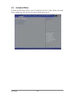
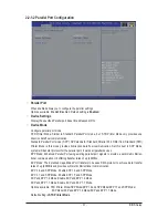
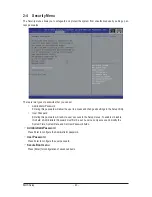
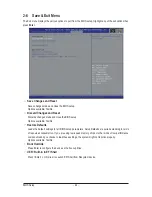
There are two types of passwords that you can set:
•
Adminstrator Password
Entering this password will allow the user to access and change all settings in the Setup Utility.
•
User Password
Entering this password will restrict a user’s access to the Setup menus. To enable or disable
this field, a Administrator Password must first be set. A user can only access and modify the
System Time, System Date, and Set User Password fields.
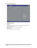
AdministratorPassword
Press Enter to configure the
Administrator password.
User Password
Press Enter to configure the user password.
Secure Boot menu
Press [Enter] for configuration of advanced items.
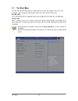
2-4 Security Menu
The Security menu allows you to safeguard and protect the system from unauthorized use by setting up ac-
cess passwords.


