User Manual 07500524
Model 3000-524
Page 11
O
peration Manual
Controls and Indicators
The following controls and indicators are provided to select and display the functions of the ASCOR
3000-524 Module’s operating environment.
3.1
VXI Logical Address
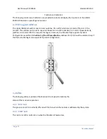
The Logical Address Switch is dual circular switches, D1 and D2 which are located at the rear of the
module. The address can be set to any value between 1 and 255 (decimal) or 1 and FF (hexadecimal),
(address 0 is reserved for the resource manager). However, the Module fully supports Dynamic
Configuration as defined in
Section F of the VXI specification,
address 255 (FF) should be selected only if
the Resource Manager also supports Dynamic Configuration.
3.2
LEDs
The following LEDs are visible at the Module’s front panel to indicate the
status of the module’s operation:
3.2.1
“BUS”
LED
This green color LED is normally off and will flash on when the module is addressed by the system.
3.2.2
“
PWR
” LED
This red color LED is normally on when the Module is Powered up.


