BIOS Setup
- 102 -
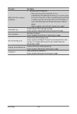
Parameter
Description
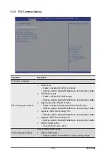
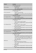
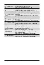
DDR4 Common Options
(continued)
Common RAS
–
Press [Enter] to configure Common RAS options.
•
Data Poisoning
•
DRAM Post Package Repair
•
RCD Parity
•
DRAM Address Command Parity Retry
•
Max Parity Error Replay
•
Write CRC Enable
•
DRAM Write CRC Enable and Retry Limit
•
Max Write CRC Error Retry
•
Disable Memory Error Injection
•
ECC Congifuration
Security
–
Press [Enter] to configure UMC security options.
•
TSME
•
Data Scramble
DRAM Memory Mapping
Press [Enter] for more options
Chipselect Interleaving
– Interleave memory blocks across the DRAM chip slects for node 0
– Options available: Disabled/Auto. Default option is
Auto
.
BankGroupSwap
–
Configures the BankGroupSwap. BankGroupSwap (BGS) is a
memory mapping option in AGESA that alters how applications get
assigned to physical locations within the memory modules. When
this option sets to Auto, it is null.
– Options available: Enabled/Disabled/Auto. Default option is
Auto
.
BankGroupSwapAlt
–
Configures the BankGroupSwapAlt.
– Options available: Enabled/Disabled/Auto. Default option is
Auto
.
Address Hash Bank
– Enable or disable bank address hashing.
– Options available: Disabled/Enabled/Auto. Default option is
Auto
.
Address Hash CS
– Enable or disable CS address hashing.
– Options available: Auto/Enabled/Disabled. Default option is
Auto
.
Address Hash Rm
– Enable or disable RM address hashing.
– Options available: Auto/Enabled/Disabled. Default option is
Auto
.
SPD Read Optimization
– Enable or disable SPD Read Optimization. Enabled = SPD reads
are skipped for Reserved fields and most of upper 256 Bytes,
Disabled = read all 512 SPD Bytes.
– Options available: Auto/Enabled/Disabled. Default option is
Auto
.
NVDIMM
Press [Enter] for more options.
Summary of Contents for G292-Z44
Page 1: ...G292 Z44 HPC Server 2U DP 8 x Gen4 GPU Server Broadcom solution User Manual Rev 1 0 ...
Page 10: ... 10 This page intentionally left blank ...
Page 16: ...Hardware Installation 16 This page intentionally left blank ...
Page 27: ... 27 System Hardware Installation 2 3 1 4 CPU0 CPU1 ...
Page 32: ...System Hardware Installation 32 For GPU7 GPU8 1 2 2 For GPU1 GPU2 Front Rear 1 ...
Page 33: ... 33 System Hardware Installation 1 2 2 3 4 ...
Page 35: ... 35 System Hardware Installation 1 1 2 2 For GPU3 GPU4 1 1 2 2 3 4 ...
Page 37: ... 37 System Hardware Installation 3 4 5 6 6 ...
Page 39: ... 39 System Hardware Installation 5 6 ...
Page 41: ... 41 System Hardware Installation ...
Page 48: ...System Hardware Installation 48 CPU Power MB Top Tray Connector 1 x 3 Power ...
Page 49: ... 49 System Hardware Installation HDD Backplane Board Signal HDD Backplane Board Power ...
Page 50: ...System Hardware Installation 50 Power Distribution Board to HDD Backplane Board Power SMD ...
Page 52: ...System Hardware Installation 52 Front Panel IO NVMe ...
Page 53: ... 53 System Hardware Installation NVMe Bo om Connector ...
Page 54: ...System Hardware Installation 54 NVMe Bo om Connector ...
Page 58: ...Motherboard Components 58 This page intentionally left blank ...
Page 82: ...BIOS Setup 82 5 2 13 SATA Configuration ...
Page 87: ... 87 BIOS Setup 5 2 18 Intel R I350 Gigabit Network Connection ...
Page 89: ... 89 BIOS Setup 5 2 19 VLAN Configuration ...
Page 93: ... 93 BIOS Setup 5 2 22 Intel R Ethernet Controller X550 ...


