- 14 -
Hardware Installation
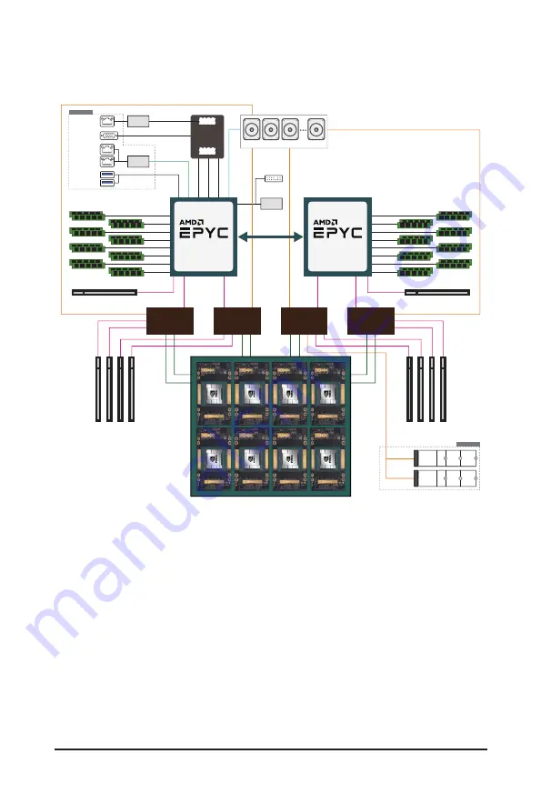
1-3 System Block Diagram
G492-ZD2 System Block Diagram
8-Channel DDR4, 16 x DIMMs
Speed up to 3200 MHz
4 x PCIe x16 slots
(rear side)
PCIe x16 slot
(front side, support MD2 card)
PCIe x16 slot
(front side, support MD2 card)
8-Channel DDR4, 16 x DIMMs
Speed up to 3200 MHz
xGMI2 18GT/s
x4 Link
BIOS
TPM
2 x 10GbE
BASE-T LAN
2 x USB 3.0
MLAN
VGA
eSPI
WAFL x1
USB2.0 x2
USB3.0 x2
ASPEED
AST2500
10/100/1G
PHY(1ch)
MAC
BMC
PCIe3.
0x
4
Intel
X710-AT2
SATA III x8
PCIe4.0 x16
NVMe x1
NVMe x2
SPI
PCIe4.0 x16
PCIe4.0 x1
6
NVMe x1
NVMe x2
PCIe4.0 x1
6
6-bay 2.5” Gen4 U.2 NVMe/ SATA
PCIe4.0 x1
6
PCIe4.0 x1
6
4 x PCIe x16 slots
(rear side)
CPU0
ROME / MILAN
“Zen3” Core
Socket SP3
PCIe Switch
PEX88096
PCIe Switch
PEX88096
PCIe Switch
PEX88096
PCIe Switch
PEX88096
CPU1
ROME / MILAN
“Zen3” Core
Socket SP3
NVIDIA HGX A100 8-GPU
NVIDIA HGX A100 8-GPU
(Delta Baseboard)
(Delta Baseboard)
NVIDIA HGX A100 8-GPU
(Delta Baseboard)
SPI Flash 32MB
Front Panel
PCIe4.0 x4
PCIe4.0 x4
M.2
M.2
CMTP062
(rear side)
Summary of Contents for G492-ZL2
Page 1: ...G492 ZL2 HPC Server 4U DP SXM4 A100 8 GPU Server User Manual Rev 1 0 ...
Page 51: ...BIOS Setup 51 When Boot Mode Select is set to Legacy in the Boot Boot Mode Select section ...
Page 63: ...BIOS Setup 63 5 2 8 PCI Subsystem Settings ...
Page 74: ... 74 BIOS Setup 5 2 17 Intel R X710 Ethernet Controller ...


