


22
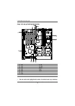
GA-8EGXDR-E(C) Motherboard
Ø
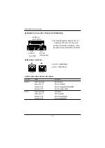
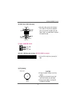
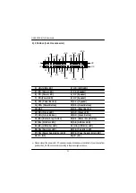
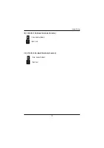
Please connect the power LED, PC speaker, reset switch and power switch etc of your chassis front
panel to the F_PANEL1 connector according to the pin assignment above.
K) F_PANEL1 (2x15 Pins connector)
-GD
+SPK
-HD
+GN
+IR
+PW +PD
-BS
+AE
-HE
+FE
NC
-RST
1
2
30
29
+HD
-IR
-PE
+PE
-FE
+HE
-AE
+BS
-GN
+GD
+RST
-PW -PDG
+PDG
-SPK
1) HD+ (HDD LED)
2) HD- (HDD LED)
3) PD- (Power LED)
4) SK-(Speaker)
5) PD- (Power LED)
6) NC (Speaker)
7) PD+(Power LED)
8) NC (Speaker)
9) PW- (Power Button)
10) SK+ (Speaker)
11) PW+ (Power Button)
12) RS+ (Reset Button)
13) KEY
14) RS- (Reset Button)
15) GD+ (Green LED)
16) GD- (Green LED)
17) GN+ (Green Button)
18) GN- (Green Button)
19 )BS+ (Buzzer Stop Button)
20) BS- (Buzzer Stop Button)
21 )AE+ (All Error LED)
22) AE- (All Error LED)
23 )HE+ (HDD Error LED)
24 ) HE- (HDD Error LED)
25) FE+ (Fan Error LED)
26) FE- (Fan Error LED)
27) PE+ (Power Supply Error LED)
28) PE- (Power Supply Error LED)
29) IR+ (NC)
30) IR- (NC)


