


5
Introduction
Form Factor
—
30.5cm x 33cm Extend ATX size form factor, 8 layers PCB.
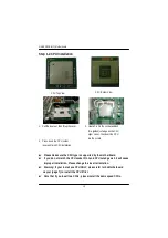
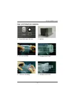
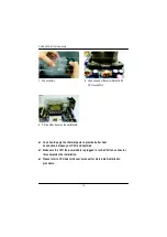
CPU
—
Dual socket 604 for Intel
®
FC-PGA Xeon processor suopprts
1.8 GB to 2.8GB and upper
—
Intel Pentium
®
4 Xeon 533MHz FSB
—
512KB internal cache depend on CPU
Chipset
—
Serverworks CMIC-SL Northbridge
—
Serverworks CIOB-X2 PCI-X Bridge
—
Serverworks CSB6 Southbridge
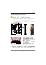
Memory
—
4 184-pin DDR DIMM sockets
—
Supports 4 ECC Register DIMM DDR 266
—
Supports up to 4 GB DRAM (Max)
—
Supports 2.5V DDR DIMM only
I/O Control
—
NS PC87417
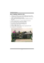
Slots
—
Support PCI-X 100MHz x 2 slots
PCI 64/66 MHz x 2 Slots
PCI 64/33 MHz x 1 Slot
PCI 32/33 MHz x 1 Slot
On-Board IDE
—
2 IDE bus master (ATA100) IDE ports for up to 4 ATAPI devices
—
1 IDE bus master (ATA66) IDE ports for up to 2 ATAPI
devices (Optioanl)
—
Support LSI software IDE RAID 0,1,5
(Optional)
On-Board Peripherals
—
1 Floppy port supports 360K, 720K,1.2M, 1.44M
and 2.88M bytes.
—
1 Parallel port supports Normal/EPP/ECP mode
—
2 COM ports (COM1 & COM2; one at front and one at rear)
—
2 LAN ports (LAN1: 10/100 ; & GLAN1: Gigabit Ethernet)
—
4 USB 1.1 (Rear USB x 2, Front USB x 2)
Hardware Monitor
—
CPU/Power/System Fan speed detection
—
CPU/Power/System Fan Control
—
CPU Overheat Warning
to be continued......
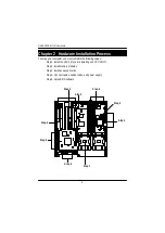
Features Summary
Chapter 1 Introduction


