


Hardware Installation
- 25 -
English
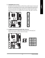
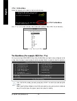
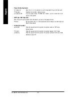
Pin No.
Definition
1
Power
2
Power
3
USB DX-
4
USB Dy-
5
USB DX+
6
USB Dy+
7
GND
8
GND
9
No Pin
10
NC
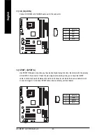
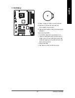
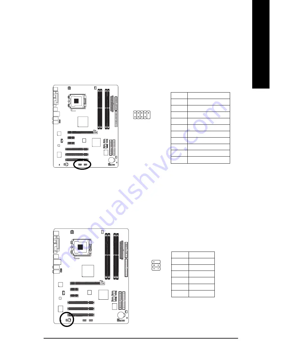
14) RF_ID
This connector allows you to connect external devices to use extra function. Check the pin
assignments before you connect the external device cable. Please contact your nearest dealer for the
optional GIGABYTE external device.
1
Pin No.
Definition
1
Power
2
RFID_RI-
3
RF_TXD
4
RF_RXD
5
NC
6
GND
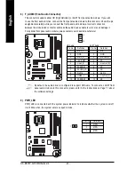
13) F_USB/GREEN_ USB (Front USB Connector)
Be careful with the polarity of the front USB connector. Check the pin assignments carefully while
you connect the front USB cable, incorrect connection between the cable and connector will make
the device unable to work or even damage it. For optional front USB cable, please contact your
local dealer. The GREEN_USB connector provides no standby power when system is off and
it does not support USB device to wake up from S3 mode. Users who wish to shut down the
standby power
(note)
for their USB devices during system power-off can connect the devices to
the GREEN_USB connector via the optional front USB cable.
(Note) When the standby power is shut down, USB devices (example: optical mouses) will not light
on during system power-off.
9
2
10
1
Summary of Contents for GA-8I945P-G-RH
Page 2: ...Motherboard GA 8I945P G RH Nov 9 2005 Nov 9 2005 Motherboard GA 8I945P G RH ...
Page 8: ... 8 ...
Page 28: ...GA 8I945P G RH Motherboard 28 English ...
Page 50: ...GA 8I945P G RH Motherboard 50 English ...
Page 54: ...GA 8I945P G RH Motherboard 54 English ...
Page 73: ...Appendix 73 English ...
Page 74: ...GA 8I945P G RH Motherboard 74 English ...
Page 75: ...Appendix 75 English ...
Page 76: ...GA 8I945P G RH Motherboard 76 English ...
Page 77: ...Appendix 77 English ...


