


Appendix
- 69 -
English
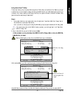
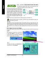
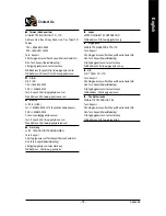
STEP 3:
After a speaker or headphone is plugged into the rear
Line Out jack, a small window will pop up and ask
you what type of equipment is connected. Choose
Headphone
or
Line Out
depending on the device
connected and click
OK
. The 2-channel audio setup
is completed.
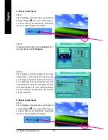
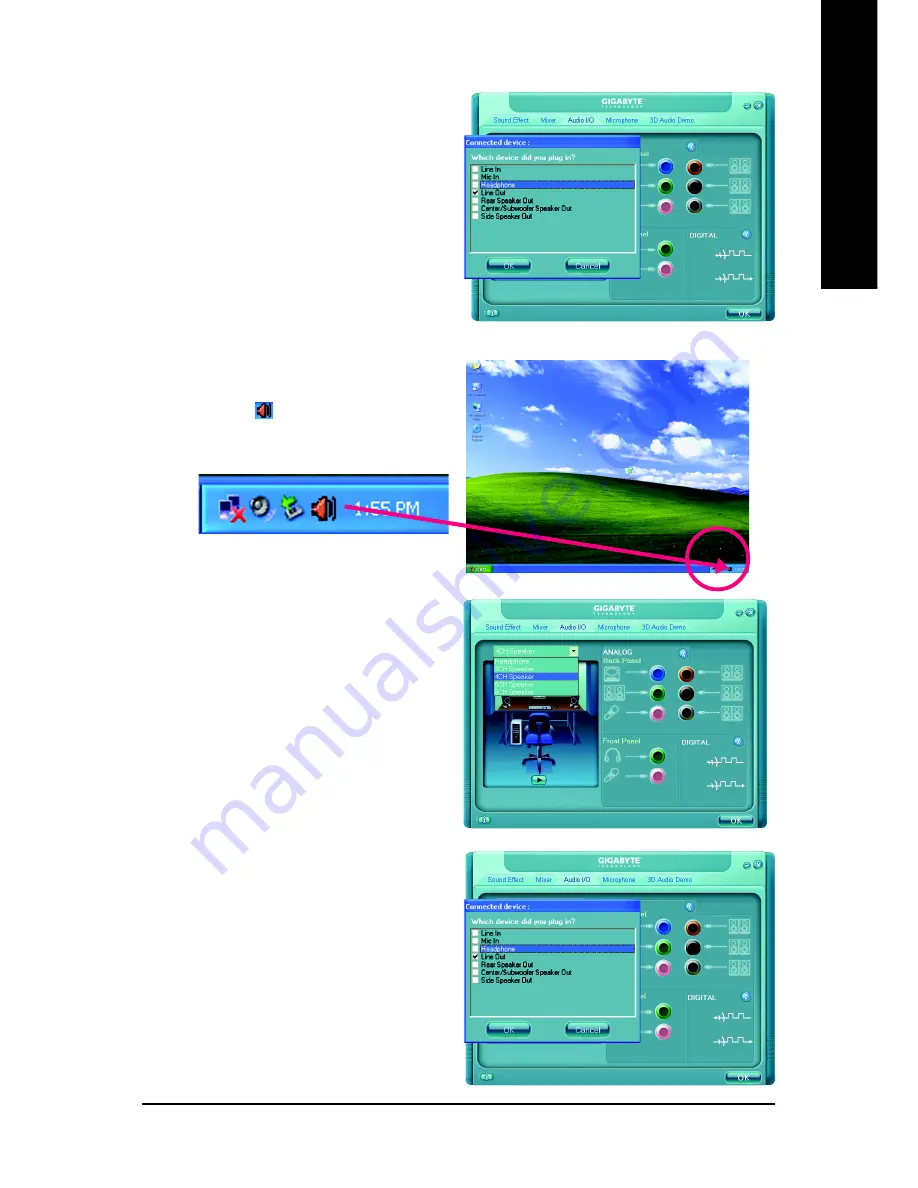
4 Channel Audio Setup
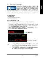
STEP 1 :
After installation of the audio driver, you should find
an Audio Manager icon in your system tray (you
can also find the icon in Control Panel). Double-click
the icon to open the Audio Control Panel.
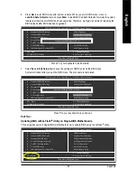
STEP 2:
In the Audio Control Panel, click the
Audio I/O
tab. In
the upper left list, click
4CH Speaker
.
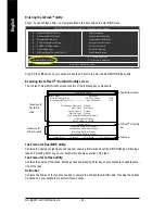
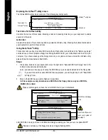
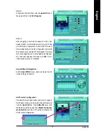
STEP 3:
After plugging in 4-channel speakers to the rear
speaker jacks, a small window will pop up and ask
you what type of equipment is connected. Choose a
device depending on the type of speaker connected
(4-channel audio consists of Front Speaker Out (Line
Out) and Rear Speaker Out and then click
OK
. The
4-channel audio setup is completed.
Summary of Contents for GA-8I945P-G-RH
Page 2: ...Motherboard GA 8I945P G RH Nov 9 2005 Nov 9 2005 Motherboard GA 8I945P G RH ...
Page 8: ... 8 ...
Page 28: ...GA 8I945P G RH Motherboard 28 English ...
Page 50: ...GA 8I945P G RH Motherboard 50 English ...
Page 54: ...GA 8I945P G RH Motherboard 54 English ...
Page 73: ...Appendix 73 English ...
Page 74: ...GA 8I945P G RH Motherboard 74 English ...
Page 75: ...Appendix 75 English ...
Page 76: ...GA 8I945P G RH Motherboard 76 English ...
Page 77: ...Appendix 77 English ...


