background image

- 35 -

BIOS Setup

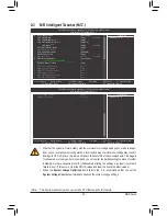
2-3  MB Intelligent Tweaker(M.I.T.)

  Whether the system will work stably with the overclock/overvoltage settings you made is depen-

dent on your overall system configurations. Incorrectly doing overclock/overvoltage may result in 

damage to CPU, chipset, or memory and reduce the useful life of these components. This page is 
for advanced users only and we recommend you not to alter the default settings to prevent system 
instability or other unexpected results. (Inadequately altering the settings may result in system's 
failure to boot. If this occurs, clear the CMOS values and reset the board to default values.)

   When the 

System Voltage Optimized

 item blinks in red, it is recommended that you set the 

System Voltage Control

 item to 

Auto

 to optimize the system voltage settings.

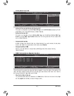
CMOS Setup Utility-Copyright (C) 1984-2011 Award Software

MB Intelligent Tweaker(M.I.T.)

  IGX Configuration 


[Press Enter]

  CPU Clock Ratio  


[Auto] 

2400Mhz


  CPU NorthBridge Freq.


[Auto]

  Core Performance Boost

 (Note)


[Enabled]


CPB Ratio

 (Note)


[Auto] 

2400Mhz


  CPU Host Clock Control 


[Auto]

x  CPU Frequency (MHz)  


 100

  PCIe Spread Spectrum   


[Disabled]

  Set Memory Clock 


[Auto]

x  Memory Clock   


 x6.66 

1333Mhz

  DRAM Configuration   


[Press Enter]

********   System Voltage Optimized    ********

  System Voltage Control  


[Auto]

x  CPU PLL Voltage Control 


Auto

x  DDR3 Voltage Control   


 Auto

x  DDR VTT Voltage Control 


Auto

x  FCH Voltage Control   


Auto

x  APU VDDP Voltage Control 


Auto

x  CPU NB VID Control   


Auto

higf

: Move 

Enter: Select 

+/-/PU/PD: Value 

F10: Save 

ESC: Exit 

F1: General Help


F5: Previous Values 

F6: Fail-Safe Defaults   

F7: Optimized Defaults

Item Help

Menu Level

 

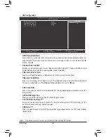
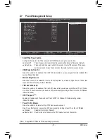
CMOS Setup Utility-Copyright (C) 1984-2011 Award Software

MB Intelligent Tweaker(M.I.T.)

higf

: Move 

Enter: Select 

+/-/PU/PD: Value 

F10: Save 

ESC: Exit 

F1: General Help


F5: Previous Values 

F6: Fail-Safe Defaults   

F7: Optimized Defaults

Item Help

Menu Level

 

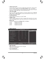
x  CPU Voltage Control   


Auto

  Normal CPU Vcore 


1.3750V

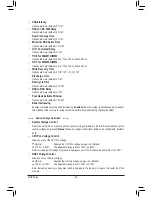
(Note)  This item is present only when you install a CPU that supports this feature.

Summary of Contents for GA-A75-D3H

Page 1: ...GA A75 D3H User s Manual Rev 1002 12ME A75D3H 1002R ...

Page 2: ...Motherboard GA A75 D3H Jun 13 2011 Jun 13 2011 Motherboard GA A75 D3H ...

Page 3: ... GIGABYTE s prior written permission Documentation Classifications Inordertoassistintheuseofthisproduct GIGABYTEprovidesthefollowingtypesofdocumentations For quick set up of the product read the Quick Installation Guide included with the product For detailed product information carefully read the User s Manual For product related information check on our website at http www gigabyte com Identifyin...

Page 4: ...iguration 16 1 4 2 Installing a Memory 17 1 5 Installing an Expansion Card 18 1 6 Setup of the AMD Dual Graphics Configuration 19 1 7 Back Panel Connectors 20 1 8 Internal Connectors 23 Chapter 2 BIOS Setup 31 2 1 Startup Screen 32 2 2 The Main Menu 33 2 3 MB Intelligent Tweaker M I T 35 2 4 Standard CMOS Features 40 2 5 Advanced BIOS Features 42 2 6 Integrated Peripherals 44 2 7 Power Management ...

Page 5: ...6 66 4 4 Q Share 67 4 5 SMART Recovery 68 4 6 Auto Green 69 Chapter 5 Appendix 71 5 1 Configuring SATA Hard Drive s 71 5 1 1 Configuring SATA Controllers 71 5 1 2 Installing the SATA RAID AHCI Driver and Operating System 77 5 2 Configuring Audio Input and Output 81 5 2 1 Configuring 2 4 5 1 7 1 Channel Audio 81 5 2 2 Configuring S PDIF Out 83 5 2 3 Enabling the Dolby Home Theater Function 84 5 2 4...

Page 6: ... 0 bracket Part No 12CR1 1UB030 5 R 2 port SATA power cable Part No 12CF1 2SERPW 0 R COM port cable Part No 12CF1 1CM001 3 R 3 5 Front Panel with 2 USB 3 0 2 0 ports Part No 12CR1 FPX582 0 R The box contents above are for reference only and the actual items shall depend on the product package you obtain The box contents are subject to change without notice ...

Page 7: ... F_PANEL COM ATX_12V AMD A75 PCIEX4 USB_ESATA CODEC PCI2 Realtek RTL8111E VGA_DVI HDMI_SPDIF USB30_LAN PCIEX1_1 M_BIOS B_BIOS CLR_CMOS SATA3_4 SATA3_0 SATA3_3 DDR3_3 DDR3_1 SPDIF_O F_USB4 F_USB1 iTE IT8720 SATA3_2 SYS_FAN2 F_AUDIO SATA3_1 TPM Etron EJ168 PCI3 PCIEX1_2 F_USB3 F_USB2 F_USB30 SYS_FAN PWR_FAN PCI1 ...

Page 8: ...ess x16 1 PCI Express x4 x4 iTE IT8720 COM Port LPC Bus Center Subwoofer Speaker Out Line Out MIC Line In S PDIF Out Side Speaker Out Surround Speaker Out CODEC 3 PCI PCI Bus PCI CLK 33 MHz Dual BIOS PCIe CLK 100 MHz PCI Express Bus PS 2 KB Mouse 4 USB 3 0 2 0 D Sub LAN RJ45 x1 Realtek RTL8111E x1 2 PCI Express x1 x16 10 USB 2 0 1 1 x1 x1 DVI D HDMI Switch 6 SATA 6Gb s AMD A75 DISP CLK 100 MHz ...

Page 9: ...y and first touch a metal object to eliminate static electricity Prior to installing the motherboard please have it on top of an antistatic pad or within an electrostatic shielding container Before unplugging the power supply cable from the motherboard make sure the power sup ply has been turned off Before turning on the power make sure the power supply voltage has been set according to the local ...

Page 10: ...ution of 2560x1600 The DVI D port does not support D Sub connection by adapter The resolution of 2560x1600 is supported only when Dual Link DVI mode is enabled 1 x HDMI port supporting a maximum resolution of 1920x1200 All integrated graphics ports do not support Hot plug If you want to change to another graphics port when the computer is on be sure to turn off the computer first Audio Realtek ALC...

Page 11: ...ports on the back panel Internal Connectors 1 x 24 pin ATX main power connector 1 x 8 pin ATX 12V power connector 5 x SATA 6Gb s connectors 1 x APU fan header 2 x system fan headers 1 x power fan header 1 x front panel header 1 x front panel audio header 1 x S PDIF Out header 4 x USB 2 0 1 1 headers 1 x USB 3 0 2 0 header 1 x serial port header 1 x Trusted Platform Module TPM header 1 x clearing C...

Page 12: ... Features Support for BIOS Support for Q Flash Support for Xpress BIOS Rescue Support for Download Center Support for Xpress Install Support for Xpress Recovery2 Support for EasyTune Available functions in EasyTune may differ by motherboard model Support for Smart Recovery Support for Auto Green Support for ON OFF Charge Support for 3TB Unlock Support for Q Share Bundled Software Norton Internet S...

Page 13: ... oriented incorrectly Apply an even and thin layer of thermal grease on the surface of the APU Do not turn on the computer if the APU cooler is not installed otherwise overheating and dam age of the APU may occur Set the APU host frequency in accordance with the APU specifications It is not recommended that the system bus frequency be set beyond hardware specifications since it does not meet the s...

Page 14: ...t in if oriented incorrectly Adjust the APU orientation if this occurs Step 1 Completely lift up the APU socket locking lever Step 2 Align the APU pin one small triangle marking with the triangle mark on the APU socket and gently insert the APU into the socket Make sure that the APU pins fit perfectly into their holes Once the APU is positioned into its socket place one finger down on the middle o...

Page 15: ...On the other side push straight down on the the APU cooler clip to hook it to the mounting lug on the reten tion frame Step 4 Turn the cam handle from the left side to the right side as the picture above shows to lock into place Refer to your APU cooler installation manual for instructions on installing the cooler Step 5 Finally attach the power connector of the APU cooler to the APU fan header CP...

Page 16: ...dwidth The four DDR3 memory sockets are divided into two channels and each channel has two memory sockets as following Channel 0 DDR3_2 DDR3_4 Channel 1 DDR3_1 DDR3_3 Dual Channel Memory Configurations Table SS Single Sided DS Double Sided No Memory DDR3_4 DDR3_2 DDR3_3 DDR3_1 Two Modules DS SS DS SS DS SS DS SS Four Modules DS SS DS SS DS SS DS SS Due to APU limitations read the following guideli...

Page 17: ...dule has a notch so it can only fit in one direction Follow the steps below to correctly install your memory modules in the memory sockets Step 1 Note the orientation of the memory module Spread the retaining clips at both ends of the memory socket Place the memory module on the socket As indicated in the picture on the left place your fin gers on the top edge of the memory push down on the memory...

Page 18: ... Secure the card s metal bracket to the chassis back panel with a screw 5 After installing all expansion cards replace the chassis cover s 6 Turn on your computer If necessary go to BIOS Setup to make any required BIOS changes for your expansion card s 7 Install the driver provided with the expansion card in your operating system Example Installing and Removing a PCI Express Graphics Card PCI slot...

Page 19: ...correct driver B Installing the Graphics Cards and Configuring BIOS Setup Step 1 Observe the steps in 1 5 Installing an Expansion Card and install an AMD Dual Graphics technology supported graphics card on the PCIEX16 slot Plug the monitor cable into the graphics card and start up your computer Step 2 Enter BIOS Setup to set the following items under the Advanced BIOS Features menu Set UMA Frame B...

Page 20: ... when Dual Link DVI mode is enabled The D Sub and HDMI ports will be disabled when Dual Link DVI mode is enabled refer to Chapter 2 BIOS Setup MB Intelligent Tweaker M I T IGX Configura tion for more information Optical S PDIF Out Connector This connector provides digital audio out to an external audio system that supports digital optical audio Before using this feature ensure that your audio syst...

Page 21: ... 1 specification Use this port for USB devices such as a USB key board mouse USB printer USB flash drive and etc eSATA 6Gb s Port The eSATA 6Gb s port conforms to SATA 6Gb s standard and is compatible with SATA 3Gb s and SATA 1 5Gb s standards Actual transfer rate is dependent on the device being connected Use the port to connect an external SATA device or a SATA port multiplier The AMD A75 Chipse...

Page 22: ...tion Side Speaker Out Jack Gray Use this audio jack to connect side speakers in a 4 5 1 7 1 channel audio configuration Line In Jack Blue The default line in jack Use this audio jack for line in devices such as an optical drive walkman etc Line Out Jack Green The default line out jack Use this audio jack for a headphone or 2 channel speaker This jack can be used to connect front speakers in a 4 5 ...

Page 23: ...d your computer Unplug the power cord from the power outlet to prevent damage to the devices After installing the device and before turning on the computer make sure the device cable has been securely attached to the connector on the motherboard 1 4 5 2 12 13 9 3 7 8 11 10 1 ATX_12V 2 ATX 3 CPU_FAN 4 SYS_FAN SYS_FAN2 5 PWR_FAN 6 BAT 7 SATA3_0 1 2 3 4 8 CLR_CMOS 9 F_PANEL 10 F_AUDIO 11 SPDIF_O 12 F...

Page 24: ...mputer will not start To meet expansion requirements it is recommended that a power supply that can withstand high power consumption be used 500W or greater If a power supply is used that does not provide the required power the result can lead to an unstable or unbootable system ATX Pin No Definition Pin No Definition 1 3 3V 13 3 3V 2 3 3V 14 12V 3 GND 15 GND 4 5V 16 PS_ON soft On Off 5 GND 17 GND...

Page 25: ... like a screwdriver to touch the positive and negative terminals of the battery holder making them short for 5 seconds 3 Replace the battery 4 Plug in the power cord and restart your computer Always turn off your computer and unplug the power cord before replacing the battery Replace the battery with an equivalent one Danger of explosion if the battery is replaced with an incorrect model Contact t...

Page 26: ...four hard drives 1 DEBUG PORT SATA3_4 7 1 1 7 7 G QBOFM DEBUG PORT G QBOFM SATA3_2 SATA3_0 SATA3_3 SATA3_1 8 CLR_CMOS Clearing CMOS Jumper Use this jumper to clear the CMOS values e g date information and BIOS configurations and reset the CMOS values to factory defaults To clear the CMOS values place a jumper cap on the two pins to temporarily short the two pins or use a metal object like a screwd...

Page 27: ...s on when the hard drive is reading or writing data RES Reset Switch Green Connects to the reset switch on the chassis front panel Press the reset switch to restart the computer if the computer freezes and fails to perform a normal restart CI Chassis Intrusion Header Gray Connects to the chassis intrusion switch sensor on the chassis that can detect if the chassis cover has been removed This funct...

Page 28: ...rmation about connecting the front panel audio module that has different wire assignments please contact the chassis manufacturer For HD Front Panel Audio ForAC 97 Front PanelAudio Pin No Definition 1 MIC2_L 2 GND 3 MIC2_R 4 ACZ_DET 5 LINE2_R 6 GND 7 FAUDIO_JD 8 No Pin 9 LINE2_L 10 GND Pin No Definition 1 MIC 2 GND 3 MIC Power 4 NC 5 Line Out R 6 NC 7 NC 8 No Pin 9 Line Out L 10 NC 11 SPDIF_O S PD...

Page 29: ... outlet to prevent damage to the USB bracket When the system is in S4 S5 mode only the USB ports routed to the F_USB1 header can sup port the ON OFF Charge function 13 F_USB30 USB 3 0 2 0 Header The header conforms to USB 3 0 2 0 specification and can provide two USB ports For purchasing the optional 3 5 front panel that provides two USB 3 0 2 0 ports please contact the local dealer Pin No Definit...

Page 30: ...10 No Pin 10 9 2 1 15 TPM Trusted Platform Module Header You may connect a TPM Trusted Platform Module to this header Pin No Definition Pin No Definition 1 LCLK 11 LAD0 2 GND 12 GND 3 LFRAME 13 NC 4 No Pin 14 ID 5 LRESET 15 SB3V 6 NC 16 SERIRQ 7 LAD3 17 GND 8 LAD2 18 NC 9 VCC3 19 NC 10 LAD1 20 SUSCLK 20 19 2 1 F_USB30 F_AUDIO H DB_PORT TPM w housing Voltage measurement module X58A OC PCIe power co...

Page 31: ... BIOS without entering the operating system BIOS is a Windows based utility that searches and downloads the latest version of BIOS from the Internet and updates the BIOS For instructions on using the Q Flash and BIOS utilities refer to Chapter 4 BIOS Update Utilities Chapter 2 BIOS Setup Because BIOS flashing is potentially risky if you do not encounter problems using the current version of BIOS i...

Page 32: ...ow the BIOS POST screen To show the BIOS POST screen at system startup refer to the instruc tions on the Full Screen LOGO Show item on page 45 DEL BIOS SETUP Q FLASH Press the Delete key to enter BIOS Setup or to access the Q Flash utility in BIOS Setup F9 XPRESS RECOVERY2 If you have ever entered Xpress Recovery2 to back up hard drive data using the driver disk the F9 key can be used for sub sequ...

Page 33: ...n the right submenus only F5 Restore the previous BIOS settings for the current submenus F6 Load the Fail Safe BIOS default settings for the current submenus F7 Load the Optimized BIOS default settings for the current submenus F8 Access the Q Flash utility F9 Display system information F10 Save all the changes and exit the BIOS Setup program F11 Save CMOS to BIOS F12 Load CMOS from BIOS If you do ...

Page 34: ...ntegrated Peripherals Use this menu to configure all peripheral devices such as SATA USB integrated audio and integrated LAN etc Power Management Setup Use this menu to configure all the power saving functions PC Health Status Use this menu to see information about autodetected system CPU temperature system voltage and fan speed etc Load Fail Safe Defaults Fail Safe defaults are factory settings f...

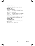
Page 35: ... M I T IGX Configuration Press Enter CPU Clock Ratio Auto 2400Mhz CPU NorthBridge Freq Auto Core Performance Boost Note Enabled CPB Ratio Note Auto 2400Mhz CPU Host Clock Control Auto x CPU Frequency MHz 100 PCIe Spread Spectrum Disabled Set Memory Clock Auto x Memory Clock x6 66 1333Mhz DRAM Configuration Press Enter System Voltage Optimized System Voltage Control Auto x CPU PLL Voltage Control A...

Page 36: ... Link DVI mode is enabled Default Disabled VGA Core Clock control Allows you to determine whether to manually set the VGA Core clock Default Auto VGA Core Clock MHz Allows you to manually set the VGA Core clock The adjustable range is from 300 MHz to 2000 MHz This item is configurable only if the VGA Core Clock control option is set to Manual CPU Clock Ratio Allows you to alter the clock ratio for...

Page 37: ... be configurable Default Auto Memory Clock This option is configurable only when Set Memory Clock is set to Manual X5 33 Sets Memory Clock to X5 33 X6 66 Sets Memory Clock to X6 66 X8 00 Sets Memory Clock to X8 00 X9 33 Sets Memory Clock to X9 33 DRAM Configuration CMOS Setup Utility Copyright C 1984 2011 Award Software DRAM Configuration DDR3 Timing Items Auto SPD Auto x 1T 2T Command Timing Auto...

Page 38: ...ving Enabled allows the system to simultaneously access dif ferent banks of the memory to increase memory performance and stability Default Enabled System Voltage Optimized System Voltage Control Determines whether to manually set the system voltages Auto lets the BIOS automatically set the system voltages as required Manual allows all voltage control items below to be configurable Default Auto CP...

Page 39: ...trol Allows you to set the APU PCIe PLL voltage Normal Supplies the APU PCIe PLL voltage as required Default 0 725V 1 835V The adjustable range is from 0 725V to 1 835V CPU NB VID Control Allows you to set the CPU NorthBridge VID voltage Normal Supplies the CPU NB VID voltage as required Default 0 600V 0 600V The adjustable range is from 0 600V to 0 600V CPU Voltage Control Allows you to set the C...

Page 40: ...ster IDE Auto Detection Press Enter to autodetect the parameters of the SATA device on this channel Extended IDE Drive Configure your SATA devices by using one of the two methods below Auto Lets the BIOS automatically detect SATA devices during the POST Default None If no SATA devices are used set this item to None so the system will skip the detection of the device during the POST for faster syst...

Page 41: ... No Errors The system boot will not stop for any error All But Keyboard The system boot will not stop for a keyboard error but stop for all other errors Default Memory These fields are read only and are determined by the BIOS POST Base Memory Also called conventional memory Typically 640 KB will be reserved for the MS DOS operating system Extended Memory The amount of extended memory ...

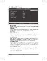
Page 42: ...I if you want to install the operating system to a hard drive larger than 2 2 TB Make sure the operating system to be installed supports booting from a GPT partition such as Windows 7 64 bit and Windows Server 2003 64 bit Auto lets the BIOS automatically configure this setting depending on the hard drive you install Default Auto First Second Third Boot Device Specifies the boot order from the avai...

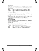
Page 43: ...dware monitor utility is installed Default Disabled Away Mode Enables or disables Away Mode in Windows XP Media Center operating system Away Mode allows the system to silently perform unattended tasks while in a low power mode that appears off Default Disabled Full Screen LOGO Show Allows you to determine whether to display the GIGABYTE Logo at system startup Disabled displays normal POST message ...

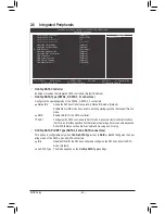
Page 44: ...nnectors This option is configurable only when OnChip SATA Type is set to RAID or AHCI Configures the oper ating mode of the SATA3_4 and eSATA connectors IDE Disables RAID for the SATA controller and configures the SATA controller to PATA mode Default As SATA Type The mode depends on the OnChip SATA Type settings CMOS Setup Utility Copyright C 1984 2011 Award Software Integrated Peripherals OnChip...

Page 45: ...efault Enabled If you wish to install a 3rd party add in network card instead of using the onboard LAN set this item to Disabled Onboard LAN Boot ROM Allows you to decide whether to activate the boot ROM integrated with the onboard LAN chip Default Disabled This motherboard incorporates cable diagnostic feature designed to detect the status of the attached LAN cable This feature will detect cablin...

Page 46: ...nables or disables the onboard audio function Default Enabled If you wish to install a 3rd party add in audio card instead of using the onboard audio set this item to Disabled Onboard USB 3 0 Controller Etron EJ168 USB controller USB 3 0 2 0 ports under PS 2 Keyboard Mouse Port Enables or disables the Etron EJ168 USB controller Default Enabled USB Controllers Enables or disables the integrated USB...

Page 47: ... Default Enabled HPET Support Note Enables or disables High Precision Event Timer HPET for Windows 7 Vista operating system Default Enabled Power On By Mouse Allows the system to be turned on by a PS 2 mouse wake up event Note To use this function you need an ATX power supply providing at least 1A on the 5VSB lead Disabled Disables this function Default Double Click Double click on left button on ...

Page 48: ...es the state of the system after the return of power from an AC power loss Soft Off The system stays off upon the return of the AC power Default Full On The system is turned on upon the return of the AC power Memory The system returns to its last known awake state upon the return of the AC power Power On by Alarm Determines whether to power on the system at a desired time Default Disabled If enabl...

Page 49: ...R FAN Fail Warning Allows the system to emit warning sound if the CPU system power fan is not connected or fails Check the fan condition or fan connection when this occurs Default Disabled CPU Smart FAN Control Enables or disables the CPU fan speed control function Enabled allows the CPU fan to run at different speed according to the CPU temperature You can adjust the fan speed with EasyTune based...

Page 50: ...ype of CPU fan installed and sets the optimal CPU fan control mode Default Voltage Sets Voltage mode for a 3 pin CPU fan PWM Sets PWM mode for a 4 pin CPU fan System Smart FAN Control Enables or disables the system fan speed control function Enabled allows the system fan to run at dif ferent speed according to the system temperature If disabled system fan runs at full speed Default Enabled ...

Page 51: ...isor Password Set User Password Save Exit Setup Exit Without Saving Load Fail Safe Defaults Y N N Press Enter on this item and then press the Y key to load the optimal BIOS default settings The BIOS defaults settings help the system to operate in optimum state Always load the Optimized defaults after updating the BIOS or after clearing the CMOS values 2 10 Load Optimized Defaults CMOS Setup Utilit...

Page 52: ... password at system startup to continue system boot In BIOS Setup you must enter the supervisor password if you wish to make changes to BIOS settings The user password only allows you to view the BIOS settings but not to make changes To clear the password press Enter on the password item and when requested for the password press Enter again The message PASSWORD DISABLED will appear indicating the ...

Page 53: ...ed Peripherals Power Management Setup PC Health Status ESC Quit Select Item F11 Save CMOS to BIOS F8 Q Flash F10 Save Exit Setup F12 Load CMOS from BIOS Load Fail Safe Defaults Load Optimized Defaults Set Supervisor Password Set User Password Save Exit Setup Exit Without Saving Save to CMOS and EXIT Y N Y Abandon all Data CMOS Setup Utility Copyright C 1984 2011 Award Software MB Intelligent Tweak...

Page 54: ...BIOS Setup 54 ...

Page 55: ... ignore the popup dialog box es e g the Found New Hardware Wizard displayed when Xpress Install is installing the drivers Failure to do so may affect the driver installation Some device drivers will restart your system automatically during the driver installation After the system restart Xpress Install will continue to install other drivers After Xpress Install installs all of the drivers a dialog...

Page 56: ...ities and applications that GIGABYTE develops and some free software You can click the Install button on the right of an item to install it 3 3 Technical Manuals This page provides GIGABYTE s application guides content descriptions for this driver disk and the mother board manuals ...

Page 57: ... 4 Contact For the detailed contact information of the GIGABYTE Taiwan headquarter or worldwide branch offices click the URL on this page to link to the GIGABYTE website 3 5 System This page provides the basic system information ...

Page 58: ...ad Center button to link to the GIGABYTE website The latest version of the BIOS drivers or applications will be displayed 3 7 New Utilities This page provides a quick link to GIGABYTE s lately developed utilities for users to install You can click the Install button on the right of an item to install it ...

Page 59: ...ard drive access speed may affect the speed at which the data is backed up restored It takes longer to back up a hard drive than to restore it System Requirements At least 512 MB of system memory VESA compatible graphics card Windows XP with SP1 or later Windows Vista Windows 7 Xpress Recovery and Xpress Recovery2 are different utilities For example a backup file created with Xpress Recovery canno...

Page 60: ...ave the backup file to the unallocated space black stripe along the top Please note that if there is no enough unallocated space Xpress Recovery2 cannot save the backup file B Accessing Xpress Recovery2 1 Boot from the motherboard driver disk to access Xpress Recovery2 for the first time When you see the following message Press any key to startup Xpress Recovery2 press any key to enter Xpress Reco...

Page 61: ...up to your hard drive in case the system breaks down The RESTORE option will not be present if no backup is created before Select REBOOT to exit Xpress Recovery2 Step 2 After the backup file is removed no backup image file will be present in Disk Management and hard drive space will be freed up Step 1 If you wish to remove the backup file select REMOVE ...

Page 62: ...ems like MS DOS or Window first Embedded in the BIOS the Q Flash tool frees you from the hassles of going through complicated BIOS flashing process What is BIOS BIOS allows you to update the system BIOS while in the Windows environ ment BIOS will download the latest BIOS file from the nearest BIOS server site and update the BIOS 4 2 1 Updating the BIOS with the Q Flash Utility A Before You Begin 1...

Page 63: ...en the update process is complete press any key to return to the main menu 2 Select HDD 0 0 and press Enter 3 Select the BIOS update file and press Enter The Save Main BIOS to Drive option allows you to save the current BIOS file Q Flash only supports USB flash drive or hard drives using FAT32 16 12 file system If the BIOS update file is saved to a hard drive in RAID AHCI mode or a hard drive atta...

Page 64: ...e Exit Setup and then press Y to save settings to CMOS and exit BIOS Setup The proce dure is complete after the system restarts Press Y to load BIOS defaults CMOS Setup Utility Copyright C 1984 2011 Award Software Load Optimized Defaults MB Intelligent Tweaker M I T Standard CMOS Features Advanced BIOS Features Integrated Peripherals Power Management Setup PC Health Status ESC Quit Select Item F11...

Page 65: ...matches your motherboard model Follow the on screen instructions to complete 2 Update the BIOS without Using the Internet Update Function Click Update BIOS from File then select the location where you save the BIOS update file obtained from the Internet or through other source Follow the on screen instructions to complete 3 Save the Current BIOS File Click Save Current BIOS to File to save the cur...

Page 66: ...formation on the installed CPU and motherboard The Memory tab provides information on the installed memory module s You can select memory module on a specific slot to see its information The Tuner tab allows you to change system clock settings and voltages Easy mode allows you to adjust the CPU FSB only Advanced mode allows you to individually change system clock settings and voltages settings usi...

Page 67: ...on area and right click on this icon to configure the data sharing settings Note This option is available only when data sharing is NOT enabled Figure 1 Data Sharing Disabled Figure 2 Data Sharing Enabled Options Descriptions Option Description Connect Displays the computers with data sharing enabled Enable Incoming Folder Enables data sharing Disable Incoming Folder Disables data sharing Open Inc...

Page 68: ...ackups the actual limit depends on the size of each partition When this limit is reached the oldest backup will be ovewritten The files folders listed on the screen are read only so you cannot edit their contents Instructions In the main menu click the Config button to open the Smart Recov ery Preference dialog box The Smart Recovery Preference dialog box Note 1 The changed data refers to the data...

Page 69: ...r the predetermined period of time After completing the settings click Set for the settings to take effect and then click Exit to quit Configuring the Bluetooth cell phone key After you select a cell phone the Add device as shown on the left will appear Enter a passkey 8 16 digits recommended which will be used for pairing with the cell phone Then enter the same passkey on your cell phone Device S...

Page 70: ...Unique Features 70 ...

Page 71: ... you do not want to create RAID you may prepare only one hard drive Windows 7 Vista XP setup disk Motherboard driver disk A USB floppy disk drive needed during Windows XP installation An empty formatted floppy disk needed during Windows XP installation 5 1 1 Configuring SATA Controllers A Installing SATA hard drive s in your computer Attach one end of the SATA signal cable to the rear of the SATA ...

Page 72: ...nnectors set On Chip SATA Type to RAID To enable RAID for the SATA3_4 eSATA connectors set OnChip SATA Type to RAID and set OnChip SATA Port4 5 Type to As SATA Type Figure 1 CMOS Setup Utility Copyright C 1984 2011 Award Software Integrated Peripherals OnChip SATA Controller Enabled OnChip SATA Type RAID OnChip SATA Port4 5 Type As SATA Type x OnChip SATA Port as ESP Press Enter Onboard LAN Functi...

Page 73: ...D Setup utility Figure 3 To view the disk drives assigned to arrays press 1 to enter the View Drive Assignments window To create an array press 2 to enter the LD View LD Define Menu window To delete an array press 3 to enter the Delete LD Menu window To view controller settings press 4 to enter the Controller Configuration window Figure 3 RAID Option ROM Version 3 3 1540 11 c 2011 Advanced Micro D...

Page 74: ...DC WD800JD 22LSA0 SATA 3G 79 89 N 02 00 WDC WD800JD 22LSA0 SATA 3G 80 02 N LD No LD Name RAID Mode Drv LD 1 Logical Drive 1 RAID 0 0 Stripe Block 64 KB Initialization Fast Gigabyte Boundary ON Read Policy Read Ahead Write Policy WriteBack Create Arrays Manually To create a new array press 2 to enter the LD View Menu window Figure 4 To create an array press Ctrl C to access the LD Define Menu Optio...

Page 75: ...n option has been selected It will erase the MBR data of the disks Press Ctrl Y key if you are sure to erase it Press any other key to ignore this option Press Ctrl Y to Modify Array Capacity or press any other key to use maximum capacity Figure 8 7 Then the message in Figure 8 will appear Press Ctrl Y to set the capacity of the RAID array or press other keys to set the array to its maximum capaci...

Page 76: ...displays whether the attached hard drives are as signed to a disk array or are unassigned Under the Assignment column drives are labeled with their as signed disk array or shown as Free if unassigned Figure 9 Option ROM Utility c 2011 Advanced Micro Devices Inc Keys Available View Drives Assignments h Up i Down PaUp PaDn Switch Page Ctrl H Secure Erase ESC Exit Port ID Drive Model Capabilities Cap...

Page 77: ...ere do you want to install Windows screen select Load Driver Step 2 Insert the motherboard driver disk and then browse to the location of the driver The locations of the drivers are as follows RAID driver for Windows 32 bit BootDrv Hw7 RAID W7 RAID driver for Windows 64 bit BootDrv Hw7 RAID W764A AHCI driver for Windows 32 bit BootDrv Hw7 AHCI W7 AHCI driver for Windows 64 bit BootDrv Hw7 AHCI W76...

Page 78: ...rv Hxp folder to your floppy disk Method B Steps 1 Use an alternative system and insert the motherboard driver disk 2 From your optical drive folder double click the Menu exe file in the BootDrv folder A Command Prompt window will open similar to that in Figure 2 3 Insert the blank formatted disk if you re using a USB floppy disk drive make sure it is designated as drive A Select the controller dr...

Page 79: ... need to install a 3rd party SCSI or RAID driver A screen will then appear asking you to specify an additional SCSI adapter Press S Windows Setup You have chosen to configure a SCSI Adapter for use with Windows using a device support disk provided by an adapter manufacturer Select the SCSI Adapter you want from the following list or press ESC to return to the previous screen ENTER Select F3 Exit A...

Page 80: ...o to Application Software Install Application Software and select AMD RAID Utility to install Then launch the AMD RAIDXpert from All Programs in the Start Menu Step 1 Enter the login ID and password default admin and then click Sign in to launch AMD RAIDXpert Step 2 Select the RAID array to be rebuilt under Logical Drive View and click the Rebuild tab in the Logi cal Drive Information pane Step 3 ...

Page 81: ...make a telephone call over the Internet and etc all at the same time A Configuring Speakers The following instructions use Windows 7 as the example operating system To install a microphone connect your microphone to the Mic in jack and manually configure the jack for microphone functionality Audio signals will be present on both of the front and back panel audio connections simultane ously If you ...

Page 82: ...vides an AC 97 front panel audio mod ule to activate the AC 97 functionality click the tool icon on the Speaker Configuration tab On the Connector Settings dialog box select the Disable front panel jack detection check box Click OK to complete Click Device advanced settings on the top right corner on the Speaker Configuration tab to open the Device advanced settings dialog box Select the Mute the ...

Page 83: ...On the Digital Output Optical screen Note click the Default Format tab and then select the sample rate and bit depth Click OK to complete 5 2 2 Configuring S PDIF Out The S PDIF Out jack can transmit audio signals to an external decoder for decoding to get the best audio quality 1 Connecting a S PDIF Out Cable Connect a S PDIF optical cable to the corresponding S PDIF out connector as shown below ...

Page 84: ...5 1 or 7 1 channel audio effects With Dolby Home Theater enabled 2 channel stereo content will be transformed into multi channel audio creating a virtual sur round sound environment Step 1 Locate the icon in the notification area and right click on this icon Select Playback devices Step 2 On the Playback tab select Speakers Then click Properties Step 3 On the Dolby tab select the Dolby Prologic II...

Page 85: ...one function ality Note The microphone functions on the front panel and back panel cannot be used at the same time Step 3 Go to the Microphone screen Do not mute the record ing volume or you ll not be able to record the sound To hear the sound being recorded during the recording process do not mute the playback volume It is recom mended that you set the volumes at a middle level Step 4 To raise th...

Page 86: ...g Devices Step 2 On the Recording tab right click on an empty space and select Show Disabled Devices Enabling Stereo Mix If the HD Audio Manager does not display the recording device you wish to use refer to the steps below The following steps explain how to enable Stereo Mix which may be needed when you want to record sound from your computer Step 3 When the Stereo Mix item appears right click on...

Page 87: ... Make sure you have connected the sound input device e g microphone to the computer 2 To record the audio click the Start Recording button 3 To stop recording audio click the Stop Recording button Be sure to save the recorded audio file upon completion B Playing the Recorded Sound You can play your recording in a digital media player program that supports your audio file format ...

Page 88: ...e onboard HD audio driver successfully For Windows XP only A Step 1 First make sure Service Pack 1 or Service Pack 2 has been installed check in My Computer Properties Gen eral System If not please update it from Microsoft s website Then make sure the Microsoft UAA Bus Driver for High Definition Audio has been installed successfully check in My Computer Properties Hardware Device Manager System De...

Page 89: ...blem is verified and solved The problem is verified and solved The problem is verified and solved No No No Yes Yes Insert the graphics card Connect the ATX main power cable and the 12V power cable Turn on the power to start the computer Make sure the motherboard does not short circuit with the chassis or other metal objects Check if the CPU cooler is attached to the CPU securely Is the pow er conn...

Page 90: ...le might fail No The problem is verified and solved The problem is verified and solved The problem is verified and solved No No Yes Yes Yes Reinstall the operating system Reinstall other devices one by one install one device at one time and then boot the system to see if the device works successfully Press Delete to enter BIOS Setup Select Load Fail Safe De faults or Load Optimized Defaults Select...

Page 91: ...es the treatment collection recycling and disposal of electric and electronic devices and their components Under the Directive used equipment must be marked collected separately and disposed of properly WEEE Symbol Statement The symbol shown below is on the product or on its packaging which indicates that this product must not be disposed of with other waste Instead the device should be taken to t...

Page 92: ...Appendix 92 ...

Page 93: ... 93 Appendix ...

Page 94: ...Appendix 94 ...

Page 95: ...e us Web address http latam giga byte com Giga Byte SINGAPORE PTE LTD Singapore WEB address http www gigabyte sg Thailand WEB address http th giga byte com Vietnam WEB address http www gigabyte vn NINGBO G B T TECH TRADING CO LTD China WEB address http www gigabyte cn Shanghai TEL 86 21 63410999 FAX 86 21 63410100 Beijing TEL 86 10 62102838 FAX 86 10 62102848 Wuhan TEL 86 27 87851061 FAX 86 27 878...

Page 96: ... address http www gigabyte cz Hungary WEB address http www giga byte hu Turkey WEB address http www gigabyte com tr Russia WEB address http www gigabyte ru Poland WEB address http www gigabyte pl Ukraine WEB address http www gigabyte ua Romania WEB address http www gigabyte com ro Serbia WEB address http www gigabyte co rs Kazakhstan WEB address http www gigabyte kz You may go to the GIGABYTE webs...

Reviews: