background image

- 41 -

BIOS Setup


`

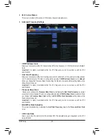
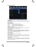
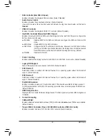
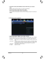
Advanced Memory Settings

(Note)  This item is present only when you install a CPU and a memory module that support this feature.


&

Extreme Memory Profile (X.M.P.) 

(Note),

 System Memory Multiplier (SPD), Memory 

Frequency(Mhz)


The settings under the three items above are synchronous to those under the same items on the 

Advanced 

Frequency Settings

 menu.


&

Performance Enhance


Allows the system to operate at three different performance levels.


Normal 


Lets the system operate at its basic performance level.


Turbo   


Lets the system operate at its good performance level. (Default)


Extreme   

Lets the system operate at its best performance level.


&

DRAM Timing Selectable 


Quick

 and 

Expert

 allows the 

Channel Interleaving

Rank Interleaving

, and memory timing settings below 

to be configurable. Options are: Auto (default), Quick, Expert.


&

Profile DDR Voltage


When using a non-XMP memory module or 

Extreme Memory Profile (X.M.P.)

 is set to 

Disabled

, this item 

will display as 

1.50V

. When 

Extreme Memory Profile (X.M.P.)

 is set to 

Profile1

 or 

Profile2

, this item will 

display the value based on the SPD data on the XMP memory.


&

Profile VTT Voltage


The value displayed here is dependent on the CPU being used.


&

Channel Interleaving


Enables or disables memory channel interleaving. 

Enabled

 allows the system to simultaneously access 

different channels of the memory to increase memory performance and stability. 

Auto

 lets the BIOS 

automatically configure this setting. (Default: Auto)


&

Rank Interleaving


Enables or disables memory rank interleaving. 

Enabled

 allows the system to simultaneously access different 

ranks of the memory to increase memory performance and stability. 

Auto

 lets the BIOS automatically 

configure this setting. (Default: Auto)

Summary of Contents for GA-X79S-UP5 User's

Page 1: ...GA X79S UP5 WIFI GA X79S UP5 User s Manual Rev 1002 12ME X79SUP5 1002R ...

Page 2: ...Motherboard GA X79S UP5 WIFI GA X79S UP5 Aug 3 2012 Aug 3 2012 Motherboard GA X79S UP5 WIFI GA X79S UP5 ...

Page 3: ...E s prior written permission Documentation Classifications In order to assist in the use of this product GIGABYTE provides the following types of documentations For quick set up of the product read the Quick Installation Guide included with the product For detailed product information carefully read the User s Manual For product related information check on our website at http www gigabyte com Ide...

Page 4: ...e Memory 16 1 4 1 4 Channel Memory Configuration 16 1 4 2 Installing a Memory 17 1 5 Installing an Expansion Card 18 1 6 Setting up AMD CrossFireX NVIDIA SLI Configuration 19 1 7 Back Panel Connectors 20 1 8 Onboard Buttons 22 1 9 Internal Connectors 23 Chapter 2 BIOS Setup 33 2 1 Startup Screen 34 2 2 The Main Menu 35 2 3 M I T 37 2 4 System 49 2 5 BIOS Features 50 2 6 Peripherals 52 2 7 Power Ma...

Page 5: ... Marvell 88SE9172 SATA Controllers 75 5 1 3 Installing the SATA RAID AHCI Driver and Operating System 81 5 2 Configuring SAS Hard Drive s 86 5 2 1 Configuring SAS Controllers 86 5 2 2 Installing the SAS RAID Driver and Operating System 92 5 3 Configuring Audio Input and Output 95 5 3 1 Configuring 2 4 5 1 7 1 Channel Audio 95 5 3 2 Configuring S PDIF Out 97 5 3 3 Configuring Microphone Recording 9...

Page 6: ...tor 5 5 One GC WB300D including two antennas one USB 2 0 cable driver disk and user s manual j 5 5 3 5 Front Panel with 2 USB 3 0 2 0 ports Optional Items 2 port USB 2 0 bracket Part No 12CR1 1UB030 6 R eSATA bracket Part No 12CF1 3SATPW 4 R 2 port IEEE 1394a bracket Part No 12CF1 1IE008 0 R The box contents above are for reference only and the actual items shall depend on the product package you ...

Page 7: ...5 HS PCI F_USB30 PCIEX1 TPM F_USB1 F_USB3 SYS_FAN1 SYS_FAN4 SYS_FAN3 SAS2 CODEC 7 6 PW_SW USB_1394_ESATA USB_ESATA USB30_LAN2 AUDIO USB30_LAN1 SYS_FAN2 Marvell 88SE9172 DDR3_4 DDR3_3 DDR3_2 DDR3_1 DDR3_5 DDR3_6 DDR3_7 DDR3_8 LGA2011 PCIEX4 VIA VT6308 PCIEX16_2 F_1394 RST_SW SAS2 5 4 SAS2 3 2 SAS2 1 0 SATA2 5 4 SATA2 3 2 SATA3 1 0 Fresco FL1009 VIA VL800 Realtek GbE LAN Intel GbE LAN iTE Super I O ...

Page 8: ...Hz LPC Bus x1 2 USB 3 0 2 0 PCI Express Bus PCI Express Bus PCIe CLK 100 MHz 1 PCI Express x1 x1 1 PCI PCI Bus PCI CLK 33 MHz CODEC 2 SATA 6Gb s LAN RJ45 x1 Marvell 88SE9172 Intel GbE LAN phy VIA VT6308 2 IEEE 1394a 4 Channel Memory 2 SATA 6Gb s 4 SATA 3Gb s x1 PCI Express Bus PCIe CLK 100 MHz Switch x16 x16 1 PCI Express x16 2 PCI Express x8 or x16 1 PCI Express x16 LAN RJ45 Realtek GbE LAN phy x...

Page 9: ...e an ESD wrist strap keep your hands dry and first touch a metal object to eliminate static electricity Prior to installing the motherboard please have it on top of an antistatic pad or within an electrostatic shielding container Before unplugging the power supply cable from the motherboard make sure the power supply has been turned off Before turning on the power make sure the power supply voltag...

Page 10: ...ce if only one PCI Express graphics card is to be installed be sure to install it in the PCIEX16_1 slot if you are installing two PCI Express graphics cards it is recommended that you install them in the PCIEX16_1 and PCIEX16_2 slots 1 x PCI Express x16 slot running at x8 PCIEX8 The PCIEX8 slot shares bandwidth with the PCIEX16_2 slot When the PCIEX8 slot is populated the PCIEX16_2 slot will opera...

Page 11: ... on the back panel 1 port available through the internal IEEE 1394a header Internal Connectors 1 x 24 pin ATX main power connector 1 x 8 pin ATX 12V power connector 2 x SATA 6Gb s connectors 4 x SATA 3Gb s connectors 8 x SAS 3Gb s connectors 1 x CPU fan header 4 x system fan headers 1 x front panel header 1 x front panel audio header 1 x S PDIF Out header 1 x USB 3 0 2 0 header 3 x USB 2 0 1 1 hea...

Page 12: ... Features Support for BIOS Support for Q Flash Support for Xpress Install Support for EasyTune Available functions in EasyTune may differ by motherboard model Support for ON OFF Charge Support for 3TB Unlock Support for Q Share Support for 3D Power Bundled Software Norton Internet Security OEM version Operating System Support for Microsoft Windows 7 Vista Form Factor E ATX Form Factor 30 5cm x 26 ...

Page 13: ... Do not turn on the computer if the CPU cooler is not installed otherwise overheating and damage of the CPU may occur Set the CPU host frequency in accordance with the CPU specifications It is not recommended that the system bus frequency be set beyond hardware specifications since it does not meet the standard requirements for the peripherals If you wish to set the frequency beyond the standard s...

Page 14: ...ith the pin one corner of the CPU socket or align the CPU notches with the socket alignment keys and carefully insert the CPU into the socket vertically Step 6 Finally secure lever A under its retention tab to complete the installation of the CPU Step 5 Once the CPU is properly inserted carefully replace the load plate Then secure lever B under its retention tab The protective plastic cover may po...

Page 15: ...ease on the surface of the installed CPU Step 4 Finally attach the power connector of the CPU cooler to the CPU fan header CPU_FAN on the motherboard Step 2 Place the cooler atop the CPU aligning the four mounting screws with the mounting holes on the ILM If your cooler has a fan grill which may cause interference when you tighten the screws remove it first and replace it after tightening the scre...

Page 16: ...ts and supports 4 Channel Technology After the memory is installed the BIOS will automatically detect the specifications and capacity of the memory The eight DDR3 memory sockets are divided into four channels and each channel has two memory sockets as following Channel A DDR3_4 DDR3_8 Channel B DDR3_2 DDR3_6 Channel C DDR3_3 DDR3_7 Channel D DDR3_1 DDR3_5 4 Channel Memory Configurations Table DDR3...

Page 17: ...pread the retaining clips at both ends of the memory socket Place the memory module on the socket As indicated in the picture on the left place your fingers on the top edge of the memory push down on the memory and insert it vertically into the memory socket Step 2 The clips at both ends of the socket will snap into place when the memory module is securely inserted Due to CPU limitations read the ...

Page 18: ...s fully seated in the slot 3 Make sure the metal contacts on the card are completely inserted into the slot 4 Secure the card s metal bracket to the chassis back panel with a screw 5 After installing all expansion cards replace the chassis cover s 6 Turn on your computer If necessary go to BIOS Setup to make any required BIOS changes for your expansion card s 7 Install the driver provided with the...

Page 19: ...formance is enabled A System Requirements Windows 7 or Windows Vista operating system A CrossFireX SLI supported motherboard with two three PCI Express x16 slots and correct driver Two three CrossFireX SLI ready graphics cards of identical brand and chip and correct driver Current GPUs that support 3 Way CrossFireX technology include the ATI Radeon HD 3800 HD 4800 HD 5800 series and AMD Radeon HD ...

Page 20: ...een LED indicates the main BIOS is active and the blue LED indicates the backup BIOS is active Clear CMOS Button Use this button to clear the CMOS values e g date information and BIOS configurations and reset the CMOS values to factory defaults when needed IEEE 1394a Port The IEEE 1394 port supports the IEEE 1394a specification featuring high speed high bandwidth and hotplug capabilities Use this ...

Page 21: ...s jack can be used to connect front speakers in a 4 5 1 7 1 channel audio configuration Mic In Jack Pink The default Mic in jack Microphones must be connected to this jack RJ 45 LAN Port LAN2 The Gigabit Ethernet LAN port provides Internet connection at up to 1 Gbps data rate The following describes the states of the LAN port LEDs Activity LED Connection Speed LED LAN Port Connection Speed LED Sta...

Page 22: ...as 2 quick buttons power button and reset button The power button and reset button allow users to quickly turn on off or reset the computer in an open case environment when they want to change hardware components or conduct hardware testing PW_SW Power button RST_SW Reset button ...

Page 23: ...er Unplug the power cord from the power outlet to prevent damage to the devices After installing the device and before turning on the computer make sure the device cable has been securely attached to the connector on the motherboard 1 ATX_12V_2X4 2 ATX 3 CPU_FAN 4 SYS_FAN1 2 3 4 5 BAT 6 SATA3 0 1 7 SATA2 2 3 4 5 8 SAS2 0 1 2 3 4 5 6 7 9 CLR_CMOS 10 F_PANEL 11 F_AUDIO 12 SPDIF_O 13 F_USB1 F_USB2 F_...

Page 24: ...er will not start To meet expansion requirements it is recommended that a power supply that can withstand high power consumption be used 500W or greater If a power supply is used that does not provide the required power the result can lead to an unstable or unbootable system 13 1 24 12 ATX ATX_12V_2X4 5 8 1 4 ATX_12V_2X4 Pin No Definition 1 GND Only for 2x4 pin 12V 2 GND Only for 2x4 pin 12V 3 GND...

Page 25: ...2 12V Speed Control 3 Sense 4 5V 5 BAT Battery The battery provides power to keep the values such as BIOS configurations date and time information in the CMOS when the computer is turned off Replace the battery when the battery voltage drops to a low level or the CMOS values may not be accurate or may be lost You may clear the CMOS values by removing the battery 1 Turn off your computer and unplug...

Page 26: ...supports a single SATA device The SATA3 0 and SATA3 1 connectors support RAID 0 and RAID 1 RAID 5 and RAID 10 can be implemented on the two connectors with the SATA2 2 3 4 5 connector Note Refer to Chapter 5 Configuring SATA Hard Drive s for instructions on configuring a RAID array 7 1 7 1 DEBUG PORT G QBOFM Pin No Definition 1 GND 2 TXP 3 TXN 4 GND 5 RXN 6 RXP 7 GND A RAID 0 or RAID 1 configurati...

Page 27: ... to be used the total number of hard drives must be an even number A RAID 10 configuration requires four hard drives SAS2 7 5 3 1 6 4 2 0 DEBUG PORT G QBOFM DEBUG PORT G QBOFM DEBUG PORT G QBOFM 9 CLR_CMOS Clear CMOS Jumper Use this jumper to clear the CMOS values e g date information and BIOS configurations and reset the CMOS values to factory defaults To clear the CMOS values use a metal object ...

Page 28: ...atus by issuing a beep code One single short beep will be heard if no problem is detected at system startup HD Hard Drive Activity LED Blue Connects to the hard drive activity LED on the chassis front panel The LED is on when the hard drive is reading or writing data RES Reset Switch Green Connects to the reset switch on the chassis front panel Press the reset switch to restart the computer if the...

Page 29: ...t wire assignments please contact the chassis manufacturer 1 12 SPDIF_O S PDIF Out Header This header supports digital S PDIF Out and connects a S PDIF digital audio cable provided by expansion cards for digital audio output from your motherboard to certain expansion cards like graphics cards and sound cards For example some graphics cards may require you to use a S PDIF digital audio cable for di...

Page 30: ... USB ports For purchasing the optional 3 5 front panel that provides two USB 3 0 2 0 ports please contact the local dealer Pin No Definition 1 Power 5V 2 Power 5V 3 USB DX 4 USB DY 5 USB DX 6 USB DY 7 GND 8 GND 9 No Pin 10 NC Pin No Definition Pin No Definition 1 VBUS 11 D2 2 SSRX1 12 D2 3 SSRX1 13 GND 4 GND 14 SSTX2 5 SSTX1 15 SSTX2 6 SSTX1 16 GND 7 GND 17 SSRX2 8 D1 18 SSRX2 9 D1 19 VBUS 10 NC 2...

Page 31: ...E 1394a Header The header conforms to IEEE 1394a specification The IEEE 1394a header can provide one IEEE 1394a port via an optional IEEE 1394a bracket For purchasing the optional IEEE 1394a bracket please contact the local dealer DEBUG PORT 10 9 2 1 Do not plug the USB bracket cable into the IEEE 1394a header Prior to installing the IEEE 1394a bracket be sure to turn off your computer and unplug ...

Page 32: ... 32 Hardware Installation ...

Page 33: ...without entering the operating system BIOS is a Windows based utility that searches and downloads the latest version of BIOS from the Internet and updates the BIOS For instructions on using the Q Flash and BIOS utilities refer to Chapter 4 BIOS Update Utilities Chapter 2 BIOS Setup Because BIOS flashing is potentially risky if you do not encounter problems using the current version of BIOS it is r...

Page 34: ... Boot Menu allows you to set the first boot device without entering BIOS Setup In Boot Menu use the up arrow key h or the down arrow key i to select the first boot device then press Enter to accept The system will boot from the device immediately Note The setting in Boot Menu is effective for one time only After system restart the device boot order will still be based on BIOS Setup settings END Q ...

Page 35: ...ration items you can click the function menu icons at the bottom of the screen or press F1 to switch to the main menu of the BIOS Setup program If a mouse is not connected the 3D BIOS screen will automatically switch to the main menu of the BIOS Setup Program B The Main Menu of the BIOS Setup Program On the main menu of the BIOS Setup program press arrow keys to move among the items and press Ente...

Page 36: ...tings to a profile or load optimized defaults for optimal performance system operations When the system is not stable as usual select the Load Optimized Defaults item to set your system to its defaults The BIOS Setup menus described in this chapter are for reference only and may differ by BIOS version BIOS Setup Program Function Keys f g Move the selection bar to select a setup menu h i Move the s...

Page 37: ...f these components This page is for advanced users only and we recommend you not to alter the default settings to prevent system instability or other unexpected results Inadequately altering the settings may result in system s failure to boot If this occurs clear the CMOS values and reset the board to default values This section provides information on the BIOS version CPU base clock CPU frequency...

Page 38: ...ng below will be changed synchronously Important It is highly recommended that the CPU frequency be set in accordance with the CPU specifications Processor Base Clock Allows you to configure the Processor Base Clock by multiplying the Host Clock Frequency by several preset host clock multipliers This item is configurable only when CPU PCIe Base Clock is enabled When you change the Processor Base C...

Page 39: ...o Turbo Ratio 1 Core Active 6 Core Active Note Allows you to set the CPU Turbo ratios for different number of active cores Auto sets the CPU Turbo ratios according to the CPU specifications Default Auto Turbo Power Limit Watts Allows you to set a power limit for CPU Turbo mode When the CPU power consumption exceeds the specified power limit the CPU will automatically reduce the core frequency in o...

Page 40: ...tion a CPU overheating protection function When enabled the CPU core frequency and voltage will be reduced when the CPU is overheated Auto lets the BIOS automatically configure this setting Default Auto CPU EIST Function Note 1 Enables or disables Enhanced Intel SpeedStep Technology EIST Depending on CPU loading Intel EIST technology can dynamically and effectively lower the CPU voltage and core f...

Page 41: ...s below to be configurable Options are Auto default Quick Expert Profile DDR Voltage When using a non XMP memory module or Extreme Memory Profile X M P is set to Disabled this item will display as 1 50V When Extreme Memory Profile X M P is set to Profile1 or Profile2 this item will display the value based on the SPD data on the XMP memory Profile VTT Voltage The value displayed here is dependent o...

Page 42: ...gurable only when DRAM Timing Selectable is set to Quick or Expert Note Your system may become unstable or fail to boot after you make changes on the memory timings If this occurs please reset the board to default values by loading optimized defaults or clearing the CMOS values Channel A B C D Timing Settings Advanced Voltage Settings ...

Page 43: ...erformance Perf Performance Balanced Mid PWR Mid Power and Lite PWR Light Power Auto lets the BIOS automatically configure this setting Default Auto Vcore Voltage Response Allows you to configure the response time for Vcore changes using preset levels Auto Lets BIOS automatically configure this setting Default Standard Fast Selects Standard or Fast which represents different levels of the response...

Page 44: ...alue The higher the V droop value the lower the output voltage will be under heavy load Auto Lets the BIOS automatically configure this setting and sets V droop following Intel specifications Default 0 180 Adjusts the V droop value CPU Vtt Loadline Calibration Allows you to configure Load Line Calibration for the CPU Vtt voltage This item allows you to adjust the V droop value The higher the V dro...

Page 45: ... threshold for the Channel A and Channel B memory area Options are 125 0o C to 135 0o C Auto lets the BIOS automatically configure this setting Default Auto DDR CH C D PWM Thermal Protection Allows you to set the PWM thermal protection threshold for the Channel C and Channel D memory area Options are 125 0o C to 135 0o C Auto lets the BIOS automatically configure this setting Default Auto CPU PWM ...

Page 46: ... Keeps or clears the record of previous chassis intrusion status Default Enabled Clears the record of previous chassis intrusion status and the Case Open field will show No at next boot Chipset Voltage Control This section provides Chipset voltage control options ...

Page 47: ... a 4 pin CPU fan that is not designed following Intel PWM fan specifications selecting PWM mode may not effectively reduce the fan speed CPU Fan Speed Control Allows you to determine whether to enable the CPU fan speed control function and adjust the fan speed Normal Allows the CPU fan to run at different speeds according to the CPU temperature You can adjust the fan speed with EasyTune based on y...

Page 48: ...cording to the system temperature You can adjust the fan speed with EasyTune based on your system requirements Default Silent Allows the system fan to run at slow speeds Manual Allows you to control the system fan speed under the Slope PWM item Disabled Allows the system fan to run at full speeds Slope PWM Allows you to control the system fan speed This item is configurable only when 2nd System Fa...

Page 49: ...lue System Time Sets the system time The time format is hour minute and second For example 1 p m is 13 0 0 Use Enter to switch between the Hour Minute and Second fields and use the Page Up or Page Down key to set the desired value Access Level Displays the current access level depending on the type of password protection used If no password is set the default will display as Administrator The Admi...

Page 50: ...lect the optical drive that contains the Windows 7 64 bit installation disk and is prefixed with UEFI string Hard Drive CD DVD ROM Drive Floppy Drive Network Device BBS Priorities Specifies the boot order for a specific device type such as hard drives optical drives floppy disk drives and devices that support Boot from LAN function etc Press Enter on this item to enter the submenu that presents th...

Page 51: ...echnology Default Disabled Intel R VT d Note Enables or disables Intel Virtualization Technology for Directed I O Default Disabled Isoc Determines whether to enable specific streams within the CPU and Chipset Default Enabled Network stack Disables or enables booting from the network to install a GPT format OS such as installing the OS from the Windows Deployment Services server Default Disable Lin...

Page 52: ...ption ROM Allows you to decide whether to activate the boot ROM integrated with the onboard LAN chip Default Disabled LAN Controller Intel GbE LAN Chip LAN1 Enables or disables the Intel GbE LAN function Default Enabled If you wish to install a 3rd party add in network card instead of using the onboard LAN set this item to Disabled ...

Page 53: ...lt Disabled Disables this function Port 0 5 Hot Plug Enables or disables the hot plug function for the SATA3 0 1 and SATA2 2 5 connectors Default Disabled Legacy USB Support Allows USB keyboard mouse to be used in MS DOS Default Enabled XHCI Hand off Determines whether to enable XHCI Hand off feature for an operating system without XHCI Hand off support Default Enabled EHCI Hand off Determines whe...

Page 54: ...ll 88SE9172 Chip eSATA connectors Enables or disables RAID for the SATA controllers integrated in the Marvell 88SE9172 chip or configures the SATA controllers to AHCI mode The area below displays the current status of the two SATA ports IDE Mode Disables RAID for the SATA controllers and configures the SATA controllers to IDE mode AHCI Mode Configures the SATA controllers to AHCI mode Advanced Hos...

Page 55: ...ault Disabled If enabled set the date and time as following Wake up day Turn on the system at a specific time on each day or on a specific day in a month Wake up hour minute second Set the time at which the system will be powered on automatically Note When using this function avoid inadequate shutdown from the operating system or removal of the AC power or the settings may not be effective High Pr...

Page 56: ...ignal from the onboard LAN Default Enabled ErP Support Determines whether to let the system consume least power in S5 shutdown state Default Disabled Note When this item is set to Enabled the following functions will become unavailable PME event wake up power on by mouse power on by keyboard and wake on LAN ...

Page 57: ...timum state Always load the Optimized defaults after updating the BIOS or after clearing the CMOS values Boot Override Allows you to select a device to boot immediately Press Enter on the device you select and select Yes to confirm Your system will restart automatically and boot from that device Save Profiles This function allows you to save the current BIOS settings to a profile You can create up...

Page 58: ...BIOS Setup 58 ...

Page 59: ...mended to install You can click the Install All button and Xpress Install will install all the recommended drivers Or click Install Single Items to manually select the drivers you wish to install Please ignore the popup dialog box es e g the Found New Hardware Wizard displayed when Xpress Install is installing the drivers Failure to do so may affect the driver installation Some device drivers will...

Page 60: ...s page displays all the utilities and applications that GIGABYTE develops and some free software You can click the Install button on the right of an item to install it 3 3 Technical Manuals This page provides the content descriptions for this driver disk ...

Page 61: ... 4 Contact For the detailed contact information of the GIGABYTE Taiwan headquarter or worldwide branch offices click the URL on this page to link to the GIGABYTE website 3 5 System This page provides the basic system information ...

Page 62: ...oad Center button to link to the GIGABYTE website The latest version of the BIOS drivers or applications will be displayed 3 7 New Program This page provides a quick link to GIGABYTE s lately developed utilities for users to install You can click the Install button on the right of an item to install it ...

Page 63: ...dow first Embedded in the BIOS the Q Flash tool frees you from the hassles of going through complicated BIOS flashing process What is BIOS BIOS allows you to update the system BIOS while in the Windows environment BIOS will download the latest BIOS file from the nearest BIOS server site and update the BIOS 4 1 1 Updating the BIOS with the Q Flash Utility A Before You Begin 1 From GIGABYTE s websit...

Page 64: ...Reboot to reboot the system 2 Select USB Flash Drive 3 Select the BIOS update file The Save BIOS to Drive option allows you to save the current BIOS file Q Flash only supports USB flash drive or hard drives using FAT32 16 12 file system If the BIOS update file is saved to a hard drive in RAID AHCI mode or a hard drive attached to an independent SATA controller use the End key during the POST to ac...

Page 65: ...ts on the Save Exit screen and press Enter to load BIOS defaults System will re detect all peripheral devices after a BIOS update so we recommend that you reload BIOS defaults Step 5 Select Save Exit Setup and press Enter And then select Yes to save settings to CMOS and exit BIOS Setup The procedure is complete after the system restarts ...

Page 66: ... Internet Update Function Click Update BIOS from GIGABYTE Server select the BIOS server site closest to your location and then download the BIOS file that matches your motherboard model Follow the on screen instructions to complete 2 Update the BIOS without Using the Internet Update Function Click Update BIOS from File then select the location where you save the BIOS update file obtained from the ...

Page 67: ...ry module on a specific slot to see its information The Tuner tab allows you to change memory settings and voltages Quick Boost mode provides you with 3 levels of CPU frequency base clock to choose to achieve desired system performance After making changes in Quick Boost mode or clicking Default to restore to default values be sure to restart your system for these changes to take effect Easy mode ...

Page 68: ...n area and right click on this icon to configure the data sharing settings Note This option is available only when data sharing is NOT enabled Figure 1 Data Sharing Disabled Figure 2 Data Sharing Enabled Options Descriptions Option Description Connect Displays the computers with data sharing enabled Enable Incoming Folder Enables data sharing Disable Incoming Folder Disables data sharing Open Inco...

Page 69: ...t is built across the SATA 6Gb s and SATA 3Gb s channels the system performance of the RAID set may vary depending on the devices being connected 5 1 1 Configuring Intel C606 SATA Controllers A Installing SATA hard drive s in your computer Attach one end of the SATA signal cable to the rear of the SATA hard drive and the other end to available SATA port on the motherboard If there is more than one...

Page 70: ...ring SATA controller mode in BIOS Setup Make sure to configure the SATA controller mode correctly in system BIOS Setup Step 1 Turn on your computer and press Delete to enter BIOS Setup during the POST Power On Self Test To create RAID set Intel SATA Controller Mode under the Peripherals menu to RAID Mode Figure 1 If you do not want to create RAID set this item to IDE Mode or AHCI Mode Step 2 Save ...

Page 71: ...s Enter Figure 3 Intel R Rapid Storage Technology enterprise SATA Option ROM 3 0 0 1184 Copyright C 2003 11 Intel Corporation All Rights Reserved RAID Volumes None defined Physical Devices ID Device Model Serial Size Type Status Vol ID 0 ST3120026AS 3JT354CP 111 7GB Non RAID Disk 1 ST3120026AS 3JT329JX 111 7GB Non RAID Disk Press CTRL I to enter Configuration Utility Intel R Rapid Storage Technolo...

Page 72: ... be set from 4 KB to 128 KB Once you have selected the stripe block size press Enter Figure 4 Figure 5 Intel R Rapid Storage Technology enterprise SATA Option ROM 3 0 0 1184 Copyright C 2003 11 Intel Corporation All Rights Reserved RAID0 Stripes data performance hi Change TAB Next ESC Previous Menu ENTER Select HELP Name Volume0 RAID Level RAID0 Stripe Disks Select Disks Strip Size 128KB Capacity ...

Page 73: ...1 Intel Corporation All Rights Reserved Press ENTER to create the specified volume hi Change TAB Next ESC Previous Menu ENTER Select HELP Name Volume0 RAID Level RAID0 Stripe Disks Select Disks Strip Size 128 KB Capacity 111 7 GB Create Volume CREATE VOLUME MENU WARNING ALL DATA ON SELECTED DISKS WILL BE LOST Are you sure you want to create this volume Y N Intel R Rapid Storage Technology enterpri...

Page 74: ...tel R Rapid Storage Technology enterprise SATA Option ROM 3 0 0 1184 Copyright C 2003 11 Intel Corporation All Rights Reserved Deleting a volume will reset the disks to non RAID WARNING ALL DISK DATA WILL BE DELETED hi Select ESC Previous Menu DEL Delete Volume HELP DELETE VOLUME MENU Name Level Drives Capacity Status Bootable Volume0 RAID0 Stripe 2 223 6GB Normal Yes ALL DATA IN THE VOLUME WILL B...

Page 75: ...roller and RAID mode in BIOS Setup Make sure to configure the SATA controller mode correctly in system BIOS Setup Step 1 Turn on your computer and press Delete to enter BIOS Setup during the POST To create RAID go to Peripherals and set GSATAController on the MarvellATAController Configuration submenu to RAID Mode Figure 2 If you do not want to create RAID set this item to IDE Mode or AHCI Mode Fi...

Page 76: ...test begins and before the operating system boot begins look for a message which says Press Ctrl M to enter BIOS Setup or Space to continue Figure 3 Press Ctrl M to enter the RAID setup utility Marvell 88SE91xx Adapter BIOS Version 1 0 1 0025 PCIe x2 5 0Gbps Mode RAID Virtual Disks No Virtual Disk Physical Disks Adapter 0 Port Disk Name Size Max Speed S0 SATA WDC WD800JD 22LSA0 76 3GB SATA 3Gb s S...

Page 77: ...pears Figure 5 Press Enter on the Create VD item ENTER SPACE Select ESC Back Exit Adapter 0 Adapter Devices RAID Vendor ID Device ID 1B4B 91A2 BIOS Version 1 0 1 0025 PCI Slot 00 IRQ Number 0A Raid Mode RAID0 RAID1 Marvell BIOS Setup c 2009 Marvell Technology Group Ltd ENTER SPACE Select ESC Back Exit Adapter Devices Marvell BIOS Setup c 2009 Marvell Technology Group Ltd RAID Delete VD Wipe out di...

Page 78: ...to quickly erase old data on the hard drives when creating the array 4 Cache Mode Select write back or write through cache 5 VD Name Enter an array name with 1 10 letters letters cannot be special characters ENTER SPACE Select ESC Back Exit Adapter Devices Marvell BIOS Setup c 2009 Marvell Technology Group Ltd RAID RAID Config Port Disk Name Size Max Speed Status S1 SATA WDC WD800JD 22LSA0 76 3GB ...

Page 79: ...he VD Y RAID Config Port Disk Name Size Max Speed Status S0 SATA WDC WD800JD 22LSA0 76 3GB SATA 3Gb s FREE S1 SATA WDC WD800JD 22LSA0 76 3GB SATA 3Gb s FREE NEXT Select free disks to create RAID Level RAID0 Max Size MB 152478 Stripe Size 64KB Quick Init NO Cache Mode WriteBack VD Name GBT Disk ID 01 Create VD NEXT ENTER SPACE Select ESC Back Exit Adapter Devices RAID Marvell BIOS Setup c 2009 Marv...

Page 80: ...nstall the utility insert the motherboard driver disk then go to Application Software Install Application Software and select Marvell Storage Utility to install Note After the installation you must login the utility with the same account name and password that you use to login the operating system If you did not set the account password before click Login to enter the Marvell Storage Utility direc...

Page 81: ...location of the driver The locations of the drivers are as follows For the Intel C606 RAID AHCI driver for Windows 32 Bit BootDrv iRST 32Bit RAID AHCI driver for Windows 64 Bit BootDrv iRST 64Bit For the Marvell 88SE9172 RAID driver for Windows 32 bit BootDrv Marvell RAID i386 RAID driver for Windows 64 bit BootDrv Marvell RAID amd64 AHCI driver for Windows 32 bit BootDrv Marvell AHCI Floppy32 AHC...

Page 82: ...r more details Intel R Rapid Storage Technology enterprise SATA Option ROM 3 0 0 1184 Copyright C 2003 11 Intel Corporation All Rights Reserved 3 Reset Disks to Non RAID 4 Exit RAID Volumes None defined Physical Disks ID Drive Model Serial Size Type Status Vol ID 0 ST3120026AS 3JT354CP 111 7GB Member Disk 0 1 WDC WD800JD 22LS WD WMAM9W736333 111 7GB Non RAID Disk hi Select ESC Exit ENTER Select Me...

Page 83: ... Then launch Intel Rapid Storage Technology enterprise from All Programs in the Start menu Step 1 On the right panel of the screen click Rebuild to another disk under Volume Properties The Status item on the right of the screen and the Information section on the bottom display the rebuild progress Step 2 Select a new drive to rebuild the RAID and click Rebuild Step 3 After the RAID volume rebuildi...

Page 84: ...utility first Enabling Automatic Rebuild Step 1 When the message Press Ctrl M to enter BIOS Setup or Space to continue appears press Ctrl M to enter the RAID setup utility On the main screen press Enter on the RAID tab and then press Enter on Spare Management Selection Adapter Devices RAID Marvell BIOS Setup c 2009 Marvell Technology Group Ltd RAID Config Port Disk Name Size Max Speed Status NEXT ...

Page 85: ...ing rebuilt When completed the status will display as Done Step 1 Under Virtual Disk 0 click the Operation tab and select Rebuild Step 2 The screen will display the new hard drive Click on the hard drive to select it and click the Submit button to begin the rebuild Step 3 Make sure you have installed the Marvell RAID driver and Marvell Storage Utility from the motherboard driver disk While in the ...

Page 86: ... drive Windows 7 Vista setup disk Motherboard driver disk RAID Levels Note 1 Skip this step if you do not want to create RAID array on the SAS controller Note 2 Required when the SAS controller is set to RAID mode 5 2 1 Configuring SAS Controllers A Installing SAS hard drive s in your computer Attach one end of the SAS signal cable to the rear of the SAS hard drive and the other end to available S...

Page 87: ...board you have and the BIOS version B Configuring SAS controller mode in BIOS Setup Make sure to configure the SAS controller mode correctly in system BIOS Setup Step 1 Turn on your computer and press Delete to enter BIOS Setup during the POST Power On Self Test To create RAID set SAS Controller under the Peripherals menu to Enabled Figure 1 Step 2 Save changes and exit BIOS Setup Figure 1 ...

Page 88: ... Intel R Rapid Storage Technology enterprise SCU Option ROM 3 1 0 2101 Copyright C 2003 12 Intel Corporation All Rights Reserved RAID Volumes None defined Physical Devices ID Device Model Serial Size Type Status Vol ID 0 ST3300657SS 134R0000N138BT4E 279 3GB Non RAID Disk 1 ST3300657SS SQEZ0000N2029LYM 279 3GB Non RAID Disk Press CTRL I to enter Configuration Utility Intel R Rapid Storage Technolog...

Page 89: ...e set from 4 KB to 128 KB Once you have selected the stripe block size press Enter Figure 4 Figure 5 Intel R Rapid Storage Technology enterprise SCU Option ROM 3 1 0 2101 Copyright C 2003 12 Intel Corporation All Rights Reserved RAID0 Stripes data performance hi Change TAB Next ESC Previous Menu ENTER Select HELP Name Volume0 RAID Level RAID0 Stripe Disks Select Disks Strip Size 128KB Capacity 530...

Page 90: ...oration All Rights Reserved Press ENTER to create the specified volume hi Change TAB Next ESC Previous Menu ENTER Select HELP Name Volume0 RAID Level RAID0 Stripe Disks Select Disks Strip Size 128 KB Capacity 530 8 GB Create Volume CREATE VOLUME MENU WARNING ALL DATA ON SELECTED DISKS WILL BE LOST Are you sure you want to create this volume Y N Intel R Rapid Storage Technology enterprise SCU Optio...

Page 91: ... to abort Figure 8 Intel R Rapid Storage Technology enterprise SCU Option ROM 3 1 0 2101 Copyright C 2003 12 Intel Corporation All Rights Reserved Deleting a volume will reset the disks to non RAID WARNING ALL DISK DATA WILL BE DELETED hi Select ESC Previous Menu DEL Delete Volume HELP DELETE VOLUME MENU Name Level Drives Capacity Status Bootable Volume0 RAID0 Stripe 2 530 8GB Normal Yes ALL DATA ...

Page 92: ...k and perform standard OS installation steps When you arrive at the Where do you want to install Windows screen select Load Driver Step 2 Insert the motherboard driver disk and then browse to the location of the driver The locations of the drivers are as follows for Windows 32 Bit BootDrv iRST SAS32 for Windows 64 Bit BootDrv iRST SAS64 Step 3 For Intel C606 select Intel R C600 Series Chipset SAS ...

Page 93: ...ls Intel R Rapid Storage Technology enterprise SCU Option ROM 3 1 0 2101 Copyright C 2003 12 Intel Corporation All Rights Reserved 3 Reset Disks to Non RAID 4 Exit RAID Volumes None defined Physical Disks ID Drive Model Serial Size Type Status Vol ID 0 ST3300657SS 134R0000N138BT4E 279 3GB Member Disk 0 1 ST3300657SS 1W9H0000N20384XF 279 3GB Non RAID Disk hi Select ESC Exit ENTER Select Menu DISK V...

Page 94: ... Then launch Intel Rapid Storage Technology enterprise from All Programs in the Start menu Step 1 On the right panel of the screen click Rebuild to another disk under Volume Properties The Status item on the right of the screen and the Information section on the bottom display the rebuild progress Step 2 Select a new drive to rebuild the RAID and click Rebuild Step 3 After the RAID volume rebuildi...

Page 95: ...peakers The following instructions use Windows 7 as the example operating system To install a microphone connect your microphone to the Mic in jack and manually configure the jack for microphone functionality To configure 4 5 1 7 1 channel audio you have to retask one of the audio jacks to be Side speaker out through the audio driver Audio signals will be present on both of the front and back pane...

Page 96: ...l audio module to activate the AC 97 functionality click the tool icon on the Speaker Configuration tab On the Connector Settings dialog box select the Disable front panel jack detection check box Click OK to complete Click Device advanced settings on the top right corner on the Speaker Configuration tab to open the Device advanced settings dialog box Select the Mute the rear output device when a ...

Page 97: ...t The S PDIF Out jack can transmit audio signals to an external decoder for decoding to get the best audio quality 1 Connecting a S PDIF Out Cable Connect a S PDIF optical cable to the corresponding S PDIF out connector as shown below and an external decoder for transmitting the S PDIF digital audio signals 2 Configuring S PDIF Out On the Digital Output Optical screen Note click the Default Format...

Page 98: ...mute the recording volume or you ll not be able to record the sound To hear the sound being recorded during the recording process do not mute the playback volume It is recommended that you set the volumes at a middle level Step 1 After installing the audio driver the HD Audio Manager icon will appear in the notification area Double click the icon to access the HD Audio Manager Step 4 To raise the ...

Page 99: ...ng Devices Step 2 On the Recording tab right click on an empty space and select Show Disabled Devices Enabling Stereo Mix If the HD Audio Manager does not display the recording device you wish to use refer to the steps below The following steps explain how to enable Stereo Mix which may be needed when you want to record sound from your computer Step 3 When the Stereo Mix item appears right click o...

Page 100: ...Make sure you have connected the sound input device e g microphone to the computer 2 To record the audio click the Start Recording button 3 To stop recording audio click the Stop Recording button Be sure to save the recorded audio file upon completion B Playing the Recorded Sound You can play your recording in a digital media player program that supports your audio file format ...

Page 101: ...lear the CMOS values before doing this please turn off the computer and unplug the power cord For motherboards that have a Clear CMOS jumper refer to the instruc tions in Chapter 1 to short the jumper to clear the CMOS values If your board doesn t have this jumper button refer to the instructions on the motherboard battery in Chapter 1 You can temporarily remove the battery from the battery holder...

Page 102: ...blem is verified and solved The problem is verified and solved The problem is verified and solved No No No Yes Yes Insert the graphics card Connect the ATX main power cable and the 12V power cable Turn on the power to start the computer Make sure the motherboard does not short circuit with the chassis or other metal objects Check if the CPU cooler is attached to the CPU securely Is the power conne...

Page 103: ...nnector or cable might fail No The problem is verified and solved The problem is verified and solved The problem is verified and solved No No Yes Yes Yes Reinstall the operating system Reinstall other devices one by one install one device at one time and then boot the system to see if the device works successfully Press Delete to enter BIOS Setup Select Load Optimized Defaults Select Save Exit Set...

Page 104: ...s the treatment collection recycling and disposal of electric and electronic devices and their components Under the Directive used equipment must be marked collected separately and disposed of properly WEEE Symbol Statement The symbol shown below is on the product or on its packaging which indicates that this product must not be disposed of with other waste Instead the device should be taken to th...

Page 105: ... 105 Appendix ...

Page 106: ...Appendix 106 ...

Page 107: ... 107 Appendix ...

Page 108: ...Appendix 108 ...

Page 109: ... 109 Appendix ...

Page 110: ...Appendix 110 ...

Page 111: ...port http rma gigabyte us Web address http latam giga byte com Giga Byte SINGAPORE PTE LTD Singapore WEB address http www gigabyte sg Thailand WEB address http th giga byte com Vietnam WEB address http www gigabyte vn NINGBO G B T TECH TRADING CO LTD China WEB address http www gigabyte cn Shanghai TEL 86 21 63410999 FAX 86 21 63410100 Beijing TEL 86 10 62102838 FAX 86 10 62102848 Wuhan TEL 86 27 8...

Page 112: ...te fr Sweden WEB address http www gigabyte se Italy WEB address http www giga byte it Spain WEB address http www giga byte es Greece WEB address http www gigabyte com gr Czech Republic WEB address http www gigabyte cz Hungary WEB address http www giga byte hu Turkey WEB address http www gigabyte com tr Russia WEB address http www gigabyte ru Poland WEB address http www gigabyte pl Ukraine WEB addr...

Reviews: