System Appearance
3 0
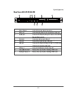
Rear View of GS-R12T4H2-RH
3
1
2 3
4
5
6
7
8
9
1.
Power Module
Connect the power cable to the socket.
2.
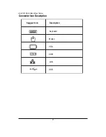
PS/2 port
Connect the keyboard and mouse devices to this port.
3.
GLAN port
Connect a RJ-45 jack to this port to link to a 10/100/1000
Megabit Ethernet LAN.
4.
Serial port
Connect serial devices to this port.
5.
VGA port
Connect the monitor device to this port.
6.
LAN port
Connect a RJ-45 jack to this port to link to a 10/100 LAN.
This port is for server management.
7.
USB port
Connect USB devices to these four ports.
8.
Low-profile riser card
Remove this cover before installing a PCIE card.
9.
Full-height riser card
Remove this cover before installing a PCIE card.
Summary of Contents for GS-R12T102
Page 20: ...20 GS R12T4H2 RH Rack Mount Server 3 4 5 6 5 6 ...
Page 27: ...27 GS R12T4H2 RH Rack Mount Server ...
Page 48: ...48 GS R12T4H2 RH Rack Mount Server Processor Configuration ...
Page 54: ...54 BIOS Setup Memory Configuration ...
Page 56: ...56 BIOS Setup Advanced Chipset Configuration ...
Page 57: ...57 GS R12T4H2 RH Rack Mount Server Figure 2 3 1 Intel VT for Directed I O VT d ...
Page 62: ...62 GS R12T4H2 RH Rack Mount Server SATA Configuration Figure 2 5 SATA Configuration ...
Page 74: ...74 BIOS Setup Server Figure 5 Server ...
Page 75: ...75 GS R12T4H2 RH Rack Mount Server System Management ...

