3 1
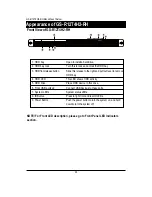
LED Description
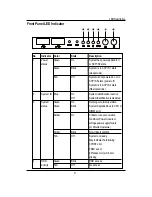
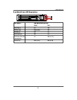
Front Panel LED Indicator
2
3
4
1
5
6
No
Indicator
1
Power
status
2
System ID
3
System
status
4
HDD
activity
Color
State
Description
Green
On
System has power applied to it
or ACPI S0 state
Green
Blink
System is in ACPI S1 state
(sleep mode)
N/A
Off
System is not powered on or in
ACPI S5 state (power off)
System is in ACPI S4 state
(hlbernate mode)
Blue
On
System identification is active
Off
System identification is disabled
Green
On
Running or normal operation
Green
Blink
System degraded due to CPU or
DIMM error
Amber
On
Critical or non-recoverable
condition (Power module or
voltage power supply failure
or critical temperature)
Amber
Blink
Non-critical condition
N/A
Off
System not ready
May indicate the following:
POST error
NMI event
Processor or terminator
missing
Green
Blink
HDD access
N/A
Off
No access
Summary of Contents for GS-R12T102
Page 20: ...20 GS R12T4H2 RH Rack Mount Server 3 4 5 6 5 6 ...
Page 27: ...27 GS R12T4H2 RH Rack Mount Server ...
Page 48: ...48 GS R12T4H2 RH Rack Mount Server Processor Configuration ...
Page 54: ...54 BIOS Setup Memory Configuration ...
Page 56: ...56 BIOS Setup Advanced Chipset Configuration ...
Page 57: ...57 GS R12T4H2 RH Rack Mount Server Figure 2 3 1 Intel VT for Directed I O VT d ...
Page 62: ...62 GS R12T4H2 RH Rack Mount Server SATA Configuration Figure 2 5 SATA Configuration ...
Page 74: ...74 BIOS Setup Server Figure 5 Server ...
Page 75: ...75 GS R12T4H2 RH Rack Mount Server System Management ...

