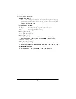
background image

6 1

GS-R12T4H2-RH Rack Mount Server
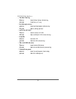
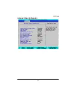
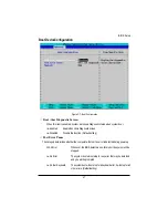
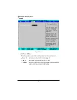
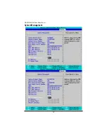
LAN2Option ROM

Enabled

Enable onboard LAN2 device and  initialize device expansion
ROM. (Default setting)

Disabled

Disable this function.

Legacy USB Support

This option allows user to function support for legacy USB.


Enabled

Enables support for legacy USB (Default setting)


Disabled

Disables support for legacy USB.

Summary of Contents for GS-R12T102

Page 1: ...Service Guide GIGABYTE GS R12T4H2 RH 1U Rack Mount Server Dual Intel Xeon LGA1366 Processor Serverboard Rev 1 0 ...

Page 2: ...overed in this generic service guide In such cases please contact your regional offices or the responsible personnel channel to provide you with further technical details 2 Please note WHEN ORDERING FRU PARTS you should check the most up to date information available on your regional web or channel For whatever reason if a part number change is made it will not be noted in the printed Service Guid...

Page 3: ...placing the FAN Duct 23 Replacing the FAN Assemblly 24 Replacing the Motherboard 25 Replacing the Power Supply 26 Replacing the Chassis Cover 28 Appearance of GS R12T4H2 RH 29 Front View of GS R12T4H2 RH 29 Rear View of GS R12T4H2 RH 30 Front Panel LED Indicator 31 LAN port LED Indicator 33 Hard Disk Drive LED Description 34 GC BS14U RH Back plane board Components 35 System Block Diagram 36 Connec...

Page 4: ...51 Memory Configuration 54 Advanced Chipset Configuration 56 PCI Configuration 60 SATA Configuration 62 I O DeviceConfiguration 65 Boot DeviceConfiguration 67 Thermal and Acoustic Configuration 69 Power 71 Security 72 Server 74 System Management 75 Console Redirection 77 Boot 79 Exit 80 ...

Page 5: ...tusageinstructions Do not use this product near water or a heat source Set up the product on a stable work surface or so as to ensure stability of the system Openingsinthecaseareprovidedforventilation Donotblockorcovertheseopenings Makesureyou provide adequate space around the system for ventilation when you set up your work area Never insert objects of any kind into the ventilation openings To av...

Page 6: ...ul interference in which case the user will be required to correct the interference at his own expense Properly shielded and grounded cables and connectors must be used in order to meet FCC emission limits Neither the provider nor the manufacturer are responsible for any radio or television interference caused by using other than recommended cables and connectors or by unauthorized changes or modi...

Page 7: ...nDepartmentofCommunicationslabelidentifiescertifiedequipment Thiscertification meansthattheequipmentmeetscertaintelecommunicationsnetworkprotective operationalandsafety requirements TheDepartmentdoesnotguaranteetheequipmentwilloperatetotheusersatisfaction Beforeinstallingthisequipment usersensurethatitispermissibletobeconnectedtothefacilitiesofthe localTelecommunicationsCompany Theequipmentmustals...

Page 8: ...s maycauseharmfulinterferencetoradiocommunication Operationofthis equipment in a residential area is likely to cause harmful interference in which case the user will be requiredtocorrecttheinterferenceatpersonalexpence However there is no guarantee that interference will not occur in a particular installation If this device does cause harmful interference to radio or television reception which can...

Page 9: ...n Multiple Bit Errors Detection Expansion Slot Tworisercards optional Full height 1 PCI E x 16 slot PCI E x8 throughput Gen2 Low profile 1 PCI E x 8 slot PCI E x8 throughput Gen2 SATA RAID controller Intel ICH10R Supports Intel Software SW RAID 0 1 10 5 Windows2008 2003 Cooling Fans Colling System 12 fans N 1 redundant Integrated LANs Controller Intel 82576EB controller support dual GbE ports Sing...

Page 10: ...nagement Functions Optional device BMC Chip Server Engine PilotII IPMI 2 0 controller FailureDetection IPMI 2 0 specification of Server management Event Logging 64KB Nonvolatile Memory to Log System Failure Events RemoteManagement Follow the IPMI 2 0 specification of Server management Environment AmbientTemperature OperatingTemperature 5o C to 35o C Non operating Temperature 0o C to 50o C Relative...

Page 11: ... and all the peripherals connected to it 3 Unplug all cables from the power outlets 4 Disconnect all telecommunication cables from their ports 5 Place the system unit on a flat and stable surface 6 Open the system according to the instructions Warning Failuretoproperlyturnofftheserverbeforeyoustartinstallingcomponents may cause serious damage Donotattempttheproceduresdescribedinthefollowingsection...

Page 12: ...Remove the chassis cover Step 1 Loosen the screw on the front chassis cover Step 2 Push down the indentation located at the side of the back chassis Step 3 Slide toward the top chassis cover Step 4 Lift up to remove the top chassis cover ...

Page 13: ...make sure the CPU type and speed that are supported by the motherboard Step1 Raise the metal locking lever on the socket Insert the CPU with the correct orientation Step2 The CPU only fits in one orientation Step3 Push the metal lever back into locked position 1 2 3 ...

Page 14: ... Place the Heat Sink on the CPU Before putting the heat sink on the CPU please well remember to apply the thermal conductivity compound on the CPU Step 2 Seat the heat sink in the retention modules with the four screws Installation completed 1 1 1 1 1 2 5 5 3 4 2 4 3 ...

Page 15: ...ot and push it down Step 2 Close the plastic clip at both edges of the DIMM slots to lock the DIMM module NOTE DIMM must be populated in order starting from DIMMA1 D1 sockets For dualquad channel operation DIMMs must be installed in matched pairs Step 3 Reverse the installation steps when you wish to remove the DIMM module 1 2 2 ...

Page 16: ... 16 17 18 11 15 No Code No Code 1 DDR_P1C2D0 10 DDR_P0C0D2 2 DDR_P1C2D1 11 DDR_P0C0D1 3 DDR_P1C2D2 12 DDR_P0C0D0 4 DDR_P1C1D0 13 DDR_P0C1D2 5 DDR_P1C1D1 14 DDR_P0C1D1 6 DDR_P1C1D2 15 DDR_P0C1D0 7 DDR_P1C0D0 16 DDR_P0C2D2 8 DDR_P1C0D1 17 DDR_P0C2D1 9 DDR_P1C0D2 18 DDR_P0C2D0 ...

Page 17: ...l Rank Single Rank Single Rank Single Rank Dual Rank Dual Rank Single Rank Dual Rank Dual Rank x x x x x x x x Single Rank Dual Rank Single Rank Single Rank Single Rank Dual Rank Dual Rank Single Rank Dual Rank Dual Rank x x x x x x x x Single Rank Dual Rank Single Rank Single Rank Single Rank Dual Rank Dual Rank Single Rank Dual Rank Dual Rank x x x x x x x x U DIMM Channel A Channel B Channel C ...

Page 18: ...nk Single Rank Dual Rank Dual Rank Single Rank Dual Rank Dual Rank Quad Rank Quad Rank Quad Rank Quad Rank x x x x x x x x x x x Single Rank Single Rank Single Rank Single Rank Dual Rank Dual Rank Dual Rank Dual Rank x x x x x x x x x x x x Single Rank Dual Rank Single Rank Single Rank Single Rank Dual Rank Quad Rank Single Rank Dual Rank Dual Rank Dual Rank Single Rank Single Rank Single Rank Sin...

Page 19: ...bracket screws Step 3 Attach the mini card to the riser bracket and ecure the mini card with screws Step 4 Attach the mini card to the riser bracket the other side Secure the mini card with screws Step 5 Slide the expansion card into the slot until the card firmly seats Step 6 Secure th expansion card with screws Step 7 Align the riser bracket to the system module 1 2 2 ...

Page 20: ...20 GS R12T4H2 RH Rack Mount Server 3 4 5 6 5 6 ...

Page 21: ...ove the HDD tray Step3 Slide hard disk into blank Step4 Secure the hard drive to the tray with four 4 screws as shown Do not over tighten the screws Slide the blank into the bay until it locks into place Step5 Engage the HDD Security Lock For detail instruction please see the following section Step6 Connect cable and power 1 2 3 4 4 ...

Page 22: ... The HDD bays incorporate a security screw to prevent accidental HDD release To engage the lock turn the security screw clock wise toward the Lock symbol To disengage the lock turn the security screw counter clock wise toward the Unlock symbol as shown ...

Page 23: ...he FAN Duct Step1 Remove the airducts from the chassis by pulling the rear edge in the direction of the arrow Step2 With fan duct installation align the fan duct with the guiding groove Push down the fan duct into chassis until its firmly seats 0 3571 1 0 3571 2 ...

Page 24: ...ss Replacing the FAN Assemblly Step1 Remove thefan assemble pulling the rear edge in the direction of the arrow Step2 Lift up the fan assembly from the chassis Step3 Reverse the previous steps to install the replacement fan assembly ...

Page 25: ...See previous sectionsfordetailinstruction Step4 Disconnectthepower SATA frontpanel andmainboardcableconnectors SeeMotherboard Placement and Jumper Setting section on page 38 Step5 Remove the elevrn 11 screws securing the mainboard in place Step6 Lift the mainboard out of the chassis in the direction of the arrow front edge first to clear the I O ports Step7 Insert the replacement mainboard rear ed...

Page 26: ...n the following image Step3 Remove the thress screws securing the power supply to the chassis Step4 Lift the power supply out of the chassis in the direction of the arrow Step5 Insert the replacement power supply and replace the two securing screws Step6 Connect the three power cables to the chassis as shown Ensure that all the cables are flush with the chassis and do not cause an obstruction ...

Page 27: ...27 GS R12T4H2 RH Rack Mount Server ...

Page 28: ...lacing the Chassis Cover Step1 Replace the cover and slide the chassis in the direction of the arrow until the locking button clicks into place Step2 Tighten the securing screw on top of the server until the locking button clicks into place ...

Page 29: ...n this to lock and unlock the HDD bay 3 HDDfrontreleasebutton Slide this release to the right and pull out lever to remove HDD bay 4 HDD LED This LED shows HDD activity 5 ODD drive Place ODD device in this drive 6 Front USB ports x2 Connect USB devices to these ports 7 System LEDs System status LEDs 9 ID Button Press to light front and rear ID LEDs 9 Power Button Push the power button to turn the ...

Page 30: ...k to a 10 100 1000 Megabit Ethernet LAN 4 Serialport Connect serial devices to this port 5 VGA port Connect the monitor device to this port 6 LAN port Connect a RJ 45 jack to this port to link to a 10 100 LAN This port is for server management 7 USB port Connect USB devices to these four ports 8 Low profile riser card Remove this cover before installing a PCIE card 9 Full heightrisercard Remove th...

Page 31: ...tate power off System is in ACPI S4 state hlbernatemode Blue On System identification is active Off Systemidentificationisdisabled Green On Runningornormaloperation Green Blink System degraded due to CPU or DIMM error Amber On Criticalornon recoverable condition Power module or voltage power supply failure orcriticaltemperature Amber Blink Non criticalcondition N A Off System not ready May indicat...

Page 32: ...er Color State Description Green On Link between system and network or no access Green Blink Network access Green On Link between system and network or no access Green Blink Network access No Indicator 5 LAN1 activity 6 LAN2 activity ...

Page 33: ... indicator 2 Link activity indicator Color State Description N A Off 10Mbpsconnection Green On 100Mbpsconnection Orange On 1000Mbpsconnection Note The server management port does not support 1000Mbpsconnection Green On Activeconnection Green Blink Transmitorreceiveconnection ...

Page 34: ...k Drive LED Description Description HDD Prsent HDD access HDD failure HDD removed HDD connected and rebuildingdata HDD locate SAS SATA HDD indicator Green Red On Off Blink 4Hz Off Off On Off On On Blink 1 Hz Blink 4Hz Blink 4Hz ...

Page 35: ... Connector 14 pin 2 P1 Power Connector 14 pin 3 14 SF1 SF12 System fan connectors 1 12 15 CD ROM_PWR1 CD ROM power connector 16 J3 CD ROM power connector 17 J2 SMBUS connector from M B to B P 18 SGPIO_JP2 SGPIO connector from RAID card 19 SGPIO_JP1 SGPIO connector from Enclosure IC Motherboard 20 23 SATA0 SATA3 SATAcable connectors 0 3 24 27 SAS0 SAS HDD connector 0 3 SAS SATA ...

Page 36: ...ersburg 24D IOH Kawela PCIEx4 RMI PILOT II LPC USB x 1 2 USB0 1 PCIE x1 ID Switch BCM5221 KVM LAN RMII ITE8720 PS 2 USBX1 4 USBX1 2 Front USB1 Front USB2 USBX1 2 SATA1 SATA2 SATA3 SATA4 SATA5 SATA6 SATAII PCIE x8 GEN2 PCIE x8 GEN2 PCIE x4 GEN1 DDR3 DDR3 DDR3 CH1 CH2 DDR3 DDR3 DDR3 DDR3 DDR3 DDR3 DDR3 DDR3 DDR3 PCIE X8 x8 bandwidth PCIE x16 x8 bandwidth SODIMM x4 bandwidth PCI slot 3 3V PCI COM1 Re...

Page 37: ...37 GS R12T4H2 RH Rack Mount Server Connector Icon Description Suggest Icon Description Keyboard VGA Mouse LAN COM USB ...

Page 38: ...38 MotherboardCompononts GA 7TTSE RH Motherboard Component Motherboard Placement and Jumper Setting 2 3 4 1 5 6 9 10 7 11 12 13 15 14 21 8 16 18 19 20 22 17 23 24 ...

Page 39: ...10 Front panel connector 11 SO DIMM I F 12 PCI 32 33 MHz slot 13 PCI E x12 slot 14 PCI E x8 slot 15 Rear I O ports 16 DDR3 DIMM slots x 9 for secondary processor 17 DDR3 DIMM slots x 9 for primary processor 18 8 pin Power connector for primary processor 19 8 pin Power connector for secondary processor 20 24 pin Power connector 21 SGPIO connector 1 for ICH10R 22 SGPIO connector 2 for RAID card 23 S...

Page 40: ...3 close Enable BIOS Recovery function 2 CLR_CMOS1 Clear CMOS jumper You may clear the CMOS data to its default values by this jumper Default value doesn t include the Shunter to prevent from improper use this jumper To clear CMOS temporarily short 2 3 pin 1 2 close Normal operation Default setting 2 3 close Clear CMOS 1 1 1 1 ...

Page 41: ...tion Defaultsetting 1 1 2 3 Close Enable BMC function 3 CLR_RTC1 Clear RTC jumper 1 1 2 3 close Clear RTC status 1 2 close Normal operation Default setting 6 7 JP_STRAP2 JP_STRAP8 PilotII firmware upgrade jumper JP_STRAP2 JP_STRAP8 Descripeion Boot from BMC BOOT SPI Interface Default setting Boot From BMC LPC BOOT ROM interface Boot From internal ROM Scratchpad Registers Boot From internal ROM Scr...

Page 42: ...iser cards installed in the PCI riser card bracket assembly povides support for both full heoghtandlow profileexpansioncards Full height and low profile PCI Express riser cards No Code Description 1 PCI E_X16_1 Full heightriserslot 2 PCI E_2 Low profileriserslot 1 2 ...

Page 43: ...d F4 Reserved F6 Reserved F7 Reserved F8 Reserved F9 LoadtheOptimizedDefaults F10 Save all the CMOS changes only for Main Menu BIOS Basic Input and Output System includes a CMOS SETUP utility which allows user to configure required settings or to activate certain system features The CMOS SETUP saves the configuration in the CMOS SRAM of the motherboard When the power is turned off the battery on t...

Page 44: ...lt settings for stability Main This setup page includes all the items in standard compatible BIOS Advanced This setup page includes all the items of Phoenix BIOS special enhanced features ex Autodetectfanandtemperaturestatus automaticallyconfigureharddiskparameters Power ThissetuppageincludesalltheitemsofGreenfunctionfeatures Security Change set or disable password It allows you to limit access th...

Page 45: ...tem Time HH MM SS BIOSInformantion BIOS Version displays the BIOS version BIOS Date displays the BIOS established date ProcessorInformation This category includes the information of CPU type Speed and number of CPU count Main Once you enter Phoenix BIOS Setup Utility the Main Menu Figure 1 will appear on the screen Use arrow keys to select among the items and press Enter to accept or enter the sub...

Page 46: ...46 BIOS Setup TotalMemory The BIOS determines how much total memory is present during the POST ...

Page 47: ...s section allowing user to configure your system for advanced operation User can set the Processor configuration Memory configuration Advanced chipset configuration PCI configuration SATAconfiguration I Odeviceconfiguration Boot configuration andThermaland acousticconfiguration ...

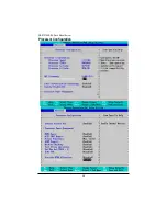
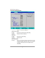
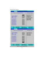
Page 48: ...48 GS R12T4H2 RH Rack Mount Server Processor Configuration ...

Page 49: ...ms and applications in independent partitions With virtualization one computer system can function as multiple virtual systems With processor and I O enhancements to Intel s various platforms Intel Virtualization Technology can improve the performance and robustness of today s software only virtual machine solutions Enabled EnableIntelVirtualizationTechnology Defaultsetting Disabled Disable this f...

Page 50: ...sable Fast String Operations SetMaxExtCPUID 3 Enabled Enable Set Max Ext CPUID 3 Disabled Disable Set Max Ext CPUID 3 Default setting EchoTPR Enabled Enable Echo TPR Disabled DisableEchoTPR Defaultsetting Discrete MTRRAllocation Enabled Enable Discrete MTRRAllocation Disabled Disable Discrete MTRRAllocation Default setting ThermalManagement Enabled EnableThermalManagement Defaultsetting Disabled D...

Page 51: ...t setting Disabled Disable EIST GV3 and C State items EIST GV3 Enabled Enable EIST GV3 Default setting Disabled Disable EIST GV3 EISTPSDFunction HW_ALL In HW_ALL mode the rpocessor hardware is responsible for coordinating theP stateamonglogicalprocessorsdependencies TheOSisresponsible for keeping the P state request up to date on all logical processors Defaultsetting ...

Page 52: ...rbo Mode can be engaged with SMT Simultanceous Multi Threading enabled and 1 to 4 cores active and is not limited to only a single core or logical processor Enabled TurboMode Defaultsetting Disabled Disable Turbo Mode T State Enabled Enable CPU T State Default setting Disabled DisableT State CPU C State Enabled Enable ACPI C State C0 C1 C1E C3 C6 and C7 Default setting Disabled Disable C State CPU...

Page 53: ...in the CST as ACPI C3 state Defaultsetting Disabled Disable CPU C7 Report Package C State Limit Desired state for the C State package limit Options C0 C1 State C3 State C6 State C7 State No Limit The default setting is No Limit ACPIMWAITextensions Enabled CST using MWAIT extension isenabled for OSPM use Default setting Disabled Disable ACPI MWAIT extensions ...

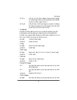
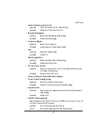
Page 54: ...54 BIOS Setup Memory Configuration ...

Page 55: ...ettings Manual Select Manual will pops up sub menu for configuration Auto Autoconfiguration Defaultsetting MemoryRASMode Identify the Memory RAS mode MemoryFrequency Select the desire value of Memory frequency Options available Auto DDR 3 800 DDR 3 1066 and DDR 3 1333 Change Interleave setting Change the interleave setting Options available 1 way 2 way 3 way 4 way and 6 way Rank Interleave setting...

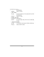
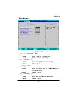
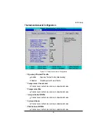
Page 56: ...56 BIOS Setup Advanced Chipset Configuration ...

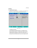
Page 57: ...57 GS R12T4H2 RH Rack Mount Server Figure 2 3 1 Intel VT for Directed I O VT d ...

Page 58: ...ort1 Port 10 Enabled Enable VT d support for Port 1 Port 10 ports throughATSR structures in ACPI Tables Default setting Disabled Disable VT d for Port1 Port 10 AdvancedChipsetControlMainMenuOptions CourseGrain ClockingGating Enabled Enable Course Grain Clocking Gating Disabled Disable Course Grain Clocking Gating Default setting Intel R I OAT Enabled Enable configuration mapped accesses to the I O...

Page 59: ...able QPI Isoch Support Default setting QPIDCASupport Enabled Enable QPI DCA Support Default setting Disabled Disable QPI DCA Support QPI scramble selection Enabled Enable QPI scramble selection Disabled Disable QPI scramble selection Default setting QPI ErrorReport Enabled Enable QPI Error Report Disabled Disable QPI Error Report Default setting MemoryECCErrorLog Identify the the memory ecc error ...

Page 60: ...ion Defualtsetting Onboard LAN1Control Enabled Enable Onboard LAN controller Defualt setting Disabled Disablethisfunction LAN1OptionROM Enabled Enable onboard LAN1 device and initialize device expansion ROM Default setting Disabled Disablethisfunction Onboard LAN2Control Enabled Enable Onboard LAN controller Defualt setting Disabled Disablethisfunction ...

Page 61: ...oard LAN2 device and initialize device expansion ROM Default setting Disabled Disablethisfunction LegacyUSBSupport This option allows user to function support for legacy USB Enabled Enables support for legacy USB Default setting Disabled Disables support for legacy USB ...

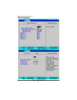
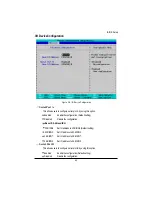
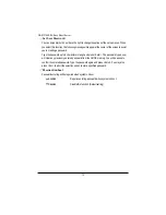
Page 62: ...62 GS R12T4H2 RH Rack Mount Server SATA Configuration Figure 2 5 SATA Configuration ...

Page 63: ...ID Enable Enabled Enabled SATARAID function Disabled Disablethisfunction Defaultsetting SATA AHCI Enable Enabled Set this item to enable SATAAHCI function for WinXP SP1 IAA driver supports AHCI mode Disabled Disabledthisfunction Defaultsetting SATA Port 0 1 2 3 4 5 The category identifies the types of Serial SATA hard disk from drive 0 to 5 that has been installed in the computer System will autom...

Page 64: ...sabled The data transfer from and to the device occurs one sector at a time Auto The data transfer from and to the device occurs multiple sectors at a time if the device supportsit LBA Mode Control This field shows if the device type in the specific IDE channel support LBA Mode 32 Bit I O Enable this function to max imize the IDE data transfer rate Transfer Mode This field shows the information of...

Page 65: ...nfiguration Base I O Address IRQ 3F8 IRQ4 Set IO address to 3F8 IRQ4 Default setting 2F8 IRQ3 Set IO address to 2F8 IRQ3 3E8 IRQ7 Set IO address to 3E8 IRQ7 2E8 IRQ5 Set IO address to 2E8 IRQ5 Serial Port B This allows users to configure serial prot B by using this option Enabled Enabletheconfiguration Defaultsetting Disabled Disabletheconfiguration Figure 2 6 I O Device Configuration ...

Page 66: ...12T4H2 RH Rack Mount Server Base I O Address IRQ 3F8 IRQ4 Set IO address to 3F8 IRQ4 2F8 IRQ3 Set IO address to 2F8 IRQ3 Default setting 3E8 IRQ7 Set IO address to 3E8 IRQ7 2E8 IRQ5 Set IO address to 2E8 IRQ5 ...

Page 67: ...st Error Pause The category determines whether the computer will stop if an error is detected during power up All Error Whenever the BIOS detects a non fatal error the system will be stopped No Error The system boot will not stop for any error that may be detected and you will be prompted All But Keyboard The system boot will not stop for a keyboard error it will stop for all othererrors Defaultse...

Page 68: ...68 GS R12T4H2 RH Rack Mount Server NumLock This option allows user to select power on state for NumLock On Enable NumLock Default setting Off Disablethisfunction ...

Page 69: ...erature Chassis inlet This item is user defined Use nuber key to adjust desired value Temperature Rise This item is user defined Use nuber key to adjust desired value Airspeed to theDIMMs This item is user defined Use nuber key to adjust desired value SystemAltitude This item is user defined Use nuber key to adjust desired value PitchbetweenDIMMs This item is user defined Use nuber key to adjust d...

Page 70: ... is user defined Use nuber key to adjust desired value Temperature Chassis inlet This item is user defined Use nuber key to adjust desired value Temperature Rise This item is user defined Use nuber key to adjust desired value Airspeed to theDIMMs This item is user defined Use nuber key to adjust desired value SystemAltitude This item is user defined Use nuber key to adjust desired value Pitchbetwe...

Page 71: ...des user to set the mode of operation if an AC power loss occurs Power On System power state when AC cord is re plugged Stay Off Do not power on system when AC power is back LastState Set system to the last sate whenAC power is removed Do not power on system whenAC power is back Default setting ...

Page 72: ...word from the CMOS memory You will be asked to confirm the entered password Type the password again and press Enter You may also press Esc to abort the selection and not enter a specified password or press Enter key to disable this option About This Section Security In this section user can set either supervisor or user passwords or both for different level of password securities In addition user ...

Page 73: ...password up to 6 characters in lengh and press Enter The password typed now will clear any previously entered password from the CMOS memory You will be asked to confirm the entered password Type the password again and press Enter You may also press Esc to abort the selection and not enter a specified password Passwordonboot Password entering will be required when system on boot Enabled Requries en...

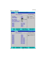
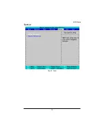
Page 74: ...74 BIOS Setup Server Figure 5 Server ...

Page 75: ...75 GS R12T4H2 RH Rack Mount Server System Management ...

Page 76: ...tegory allows user to view the system management features Including information of MotherboardHardwareinformationandsoftwareinformation BMC IPAddress Source Address obtained by BMC running DHCP or Static address Option available DHCP Static ...

Page 77: ...therboard to run console redirection function On board COM A Use Serial Port A as the COM port address On board COM B Use Serial Port B as the COM port address Disabled Disablethisfunction Defaultsetting FlowControl This option provide user to enable the flow control function None Notsupported XON XOFF Software control CTS RTS Hardwarecontrol Defaultsetting BaudRate ...

Page 78: ...is option allows user to select the specified terminal type This is defined by IEEE Options VT100 VT100 8bit PC ANSI 7bit PC ANSI VT100 VT UTF8 ASCII Continue C R after POST This option allows user to enable console redirection after O S has loaded On Enable console redirection after O S has loaded Off Disablethisfunction Defaultsetting ...

Page 79: ...e boot sequence from the available devices If the first device is not a bootable device the system will seek for next available device Key used to view or configure devices Up and Down arrows select a device and moves the device up or down f and r specifies the device fixed or removable x exclude or include the device to boot Shift 1 Enable or disable a device 1 4 Loads default boot secquence ...

Page 80: ...anges Press Enter on this item to ask for the following confirmation message Pressing Y to store all the present setting values tha user made in this time into CMOS Therefore whenyou boot up your computer next time the BIOS will re configure your system according data in CMOS ExitDiscarding Changes This option allows user to exit system setup without changing anyprevious settings values in CMOS Th...

Page 81: ...tings for all the items in the Setup utility Press the Y key to indicate Yes and then press Enter to install the optimal settings Discard Changes Select this item and press Enter to discard any changes you have made without leaving the setuputility Save Changes This option allows user to save setup dat ato CMOS Press Yes to save setup data to CMOS ...

Reviews: