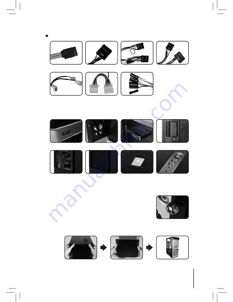
Cable Kit
(Refer to the figures below for the cable connectors)
eSATA
IEEE1394
(Multi-connectors)
Audio (HD & AC’97)
USB 2.0
Fan 3-Pin Connector
Power SW / Reset SW /
Speaker Connector
Power LED 4-pin Connector
Disc Storage
Red Led
Latch / Security Lock
2.5” enclosure docking
Multi-Media I/O port
Power Switch
Transparent side panel
Ventilated mesh side panel
1-2 Casing’s Panel Structure
1-3 Removal of Side and Front Panels
1-3.1 To remove side panels:
1-3.2 To remove front panel:
1-3.2a. Remove the left and right side panels (see step 1-3.1 on page 5), release the 6 clamps that
hold the front panel onto the chassis.
1-3.1a. Remove the 6 thumb screws at the rear of the side panel, and
detach the side panels.
05
English


