background image

Copyright

© 2018 GIGA-BYTE TECHNOLOGY CO., LTD. All rights reserved.

The trademarks mentioned in this manual are legally registered to their respective owners.

Disclaimer

Information in this manual is protected by copyright laws and is the property of GIGABYTE. 

Changes to the specifications and features in this manual may be made by GIGABYTE without 

prior notice. No part of this manual may be reproduced, copied, translated, transmitted, or pub-

lished in any form or by any means without GIGABYTE's prior written permission.

Documentation Classifications

In order to assist in the use of this product, GIGABYTE provides the following types of documentations:


  For detailed product information, carefully read the User's Manual.

For More Information

For related product specifications, the latest firmware and software, and related information, please visit 

our website at:

http://www.gigabyte.com

For GIGABYTE distributors and resellers, additional sales & marketing materials are available from our 

reseller portal:

http://reseller.b2b.gigabyte.com

For further information & technical assistance, please contact your GIGABYTE sales representative.

You may also message GIGABYTE server directly by email, Facebook or twitter

Email:

 server.grp@gigabyte.com

Facebook:

 https://www.facebook.com/gigabyteserver 

Twitter:

 https://twitter.com/GIGABYTEServer 

Summary of Contents for R161-R13

Page 1: ...R161 R13 1U Intel X299 Server System Service Guide Rev 1 0 ...

Page 2: ...cations Inordertoassistintheuseofthisproduct GIGABYTEprovidesthefollowingtypesofdocumentations For detailed product information carefully read the User s Manual For More Information For related product specifications the latest firmware and software and related information please visit ourwebsiteat http www gigabyte com For GIGABYTE distributors and resellers additional sales marketing materials a...

Page 3: ...guide NOTE Gives bits and pieces of additional information related to the current topic CAUTION Gives precautionary measures to avoid possible hardware or software problems WARNING Alerts you to any damage that might result from doing or not doing specific actions ...

Page 4: ...ticular attention to the plug electrical outlet and the point where the cord extends from the server WARNING To reduce the risk of personal injury from hot surfaces allow the drives and the internal system components to cool before touching them WARNING This server is equipped with high speed fans Keep away from hazardous moving fan blades during servicing CAUTION Do not operate the server for lon...

Page 5: ...charge ESD and ESD protection ESD can damage drives boards and other parts We recommend that you perform all procedures in this chapter only at an ESD workstation If one is not available provide some ESD protection by wearing an antistatic wrist strap attached to chassis ground any unpainted metal surface on the server when handling parts ESD and handling boards Always handle boards carefully They...

Page 6: ...on if battery is replaced incorrectly or with an incorrect type Replace the battery only with the same or equivalent type recommended by the manufacturer Dispose of used bat teries according to the manufacturer s instructions ...

Page 7: ... System Hardware Installation 19 3 1 Removing Chassis Cover 20 3 2 Installing the CPU 21 3 3 2 3 Installing the Heat Sink 22 3 4 Installing the Memory 23 3 4 1 Four Channel Memory Configuration 23 3 4 2 Installing a Memory 24 3 4 3 DIMM Population Table 24 3 5 Installing the PCI Expansion Card 25 3 6 Installing the Hard Disk Drive 26 3 7 Replacing the FAN Assemblly 27 3 8 Replacing the Power Suppl...

Page 8: ... 8 This page intentionally left blank ...

Page 9: ... 9 This page intentionally left blank ...

Page 10: ...s dry and first touch a metal object to eliminate static electricity Prior to installing the motherboard please have it on top of an antistatic pad or within an electrostatic shielding container Before unplugging the power supply cable from the motherboard make sure the power supply has been turned off Before turning on the power make sure the power supply voltage has been set according to the loc...

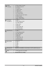
Page 11: ...ocket Socket Expansion Slot 1 x PCIe x16 slots Gen3 x16 Low profile half length The PCIe slot is unavailable for system level The PCIe slot is shared with riser card 1 x PCIe x16 signal Riser Card CRS1027 1 x PCIe x16 slots Gen3 x16 Low profile half length 1 x PCIe x16 slots Gen3 x16 Low profile half length 2 x M 2 slots M key PCIe Gen3 x4 Supports NGFF 2242 2260 2280 cards Socket Socket Video Int...

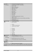
Page 12: ...on with LED 1 x ID button with LED 1 x Reset button 1 x NMI button 1 x System status LED 1 x HDD activity LED 2 x LAN activity LEDs Socket Socket Rear Panel I O 2 x USB 3 0 1 x Power button with LED 1 x ID button with LED 1 x Reset button 1 x NMI button 1 x System status LED 1 x HDD activity LED 2 x LAN activity LEDs Socket Socket Rear I O Port 2 x USB 3 0 1 x VGA 1 x COM 2 x RJ45 1 x MLAN Socket ...

Page 13: ...Serial Over LAN vKVM vMedia HTML5 Socket Socket Power Supply 1 x 850W redundant PSUs 80 PLUS Platinum AC Input 100 240V 12 6A 50 60Hz 200 240V 8A 50 60Hz DC Output Max 850W 12V 70 5A 5V 20A 3 3V 20A 12V 0 5A 5Vsb 3 0A Socket Socket Environment Ambient Temperature Relative Humidity Operating temperature 10 C to 35 C Non operating temperature 40 C to 60 C Operating humidity 8 80 non condensing Non o...

Page 14: ... 14 Hardware Installation 1 3 System Block Diagram ...

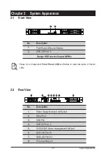
Page 15: ... to Chapter 2 3 Front Panel LED and Buttons for detail description of function LEDs 2 2 Rear View No Description 1 Power Supply Module Cord Socket 2 Serial Port 3 VGA Port 4 USB 3 0 Port x 2 5 10 100 1000 Server management LAN port 6 GbE LAN Port 1 7 GbE LAN Port 2 8 PCIe Card Bay x 2 HDD 0 HDD 1 HDD 2 HDD 3 HDD 4 NVMe Compa bile HDD 5 NVMe Compa bile 1 2 1 2 3 4 5 6 7 8 ...

Page 16: ...ss or no HDD fault 5 6 LAN 1 2 Active Link LEDs Green Solid On Link between system and network or no access Green Blink Data trasmission or receiving is occuring N A Off No data transmission or receiving is occuring 7 System Status LED Green Solid On System is operating normally Amber Solid On Critical condition may indicate System fan failure System temperature Blink Non critical condition may in...

Page 17: ... Speed LED Yellow On 1 Gbps data rate Green On 100 Mbps data rate N A Off 10 Mbps data rate 2 1GbE Link Activity LED Green On Link between system and network or no access Blink Data transmission or receiving is occurring N A Off No data transmission or receiving is occurring 2 1 2 1 2 1 ...

Page 18: ...oved HDD Slot LED on Back Panel Disk LED Removed HDD Slot Green ON 1 OFF Green OFF ON OFF ON 1 OFF OFF ON OFF ON Alternately Low Speed 2 Hz 3 3 OFF OFF Green Amber Green ON 1 OFF Green Green OFF OFF Amber Amber Amber OFF OFF Amber OFF LED 2 HDD Present No HDD Green ON OFF NOTE 1 Depends on HBA Utility Spec 2 Blink cycle depends on HDD s activity signal 3 If HDD is pulled out during rebuilding the ...

Page 19: ...ver you are working inside the computer case If possible wear a grounded wrist strap when you are working inside the computer case Alternatively discharge any static electricity by touching the bare metal system of the computer case or the bare metal body of any other grounded appliance Hold electronic circuit boards by the edges only Do not touch the components on the board unless it is necessary...

Page 20: ...to AC power Follow these instructions to remove the system cover 1 Loosen and the two thumbscrew at the rear of the system 2 Remove the single secrew at the front of the system 3 Push down the indentation located at the side of the back chassis 4 Using the grip areas on the top cover and slide the cover horizontally in the direction of the arrow 3 4 3 2 1 ...

Page 21: ...stem unit on a flat and stable surface Open the system according to the instructions WARNING Failure to properly turn off the server before you start installing components may cause serious damage Do not attempt the procedures described in the following sections unless you are a qualified service technician Follow these instructions to install the CPU 1 Raise the metal locking lever on the socket ...

Page 22: ... install the heat sinks 1 Apply thermal compound evenly on the top of the CPU 2 Remove the protective cover from the underside of the heat sink 3 Place the heat sink s on top of the CPU and tighten the four positioning screws 1 2 3 3 2 3 Installing the Heat Sink ...

Page 23: ...h Read the following guidelines before you begin to install the memory Make sure that the motherboard supports the memory It is recommended that memory of the same capacity brand speed and chips be used Always turn off the computer and unplug the power cord from the power outlet before installing the memory to prevent hardware damage Memory modules have a foolproof design A memory module can be in...

Page 24: ...odule vertically into the DIMM slot and push it down 2 Close the plastic clip at both edges of the DIMM slots to lock the DIMM module 3 Reverse the installation steps when you want to remove the DIMM module 1 2 2 3 4 3 DIMM Population Table DIMM Capacity GB 1 Slot per Channel 2 Slot per Channel DIMM Density Speed MT s Voltage V Slot Per Channel SPC DIMM Per Channel DPC 1DPC 1DPC 2DPC 1 2V 2666 266...

Page 25: ...mage to equipment The PCI riser assembly does not include a riser card or any cabling as standard To install a PCI card a riser card must be installed Follow these instructions to PCI Expansion card 1 Remove the securing special screw on the riser bracket 2 Loosen the thumbscrew on the riser bracket 3 Lift up the riser bracket out of system 4 Remove the slot covers from the riser bracket 5 Orient ...

Page 26: ...tray will not fit back into the bay if inserted incorrectly Make sure that the HDD is connected to the HDD connector on the backplane Follow these instructions to install a hard disk drive 1 Press the release button 2 Extend the locking lever and pull the locking lever to remove the HDD tray 3 Place the hard disk drive into the HDD tray 4 Secure the hard disk drive to the HDD tray with four screws...

Page 27: ...are Installation 3 7 Replacing the FAN Assemblly Follow these instructions to replace the fan assembly 1 Lift up the fan assembly from the chassis 2 Reverse the previous steps to install the replacement fan assembly 1 ...

Page 28: ... to replace the power supply 1 Remove the screws securing power supply 2 Slide the power supply inward to remove the power supply from the system 3 Insert the replacement power supply firmly into the chassis Connect the AC power cord to the replacement power supply 1 1 Screw Screw Screw 2 ...

Page 29: ...able Routing System Power Cable OLD_REV OLD_REV OLD_REV OLD_REV Front IO Board Power Cable Front IO Board Power Cable Front Panel USB 3 0 Cable OLD_REV OLD_REV OLD_REV OLD_REV OLD_REV OLD_REV OLD_REV OLD_REV OLD_REV OLD_REV OLD_REV OLD_REV ...

Page 30: ... Plane Board Power Cable HDD Back Plane Board Signal Cable OLD_REV OLD_REV OLD_REV OLD_REV OLD_REV OLD_REV OLD_REV OLD_REV On Board SATA to HDD Back Plane Board Cable NVMe Cable OLD_REV OLD_REV OLD_REV OLD_REV OLD_REV OLD_REV OLD_REV OLD_REV ...

Page 31: ...EV OLD_REV OLD_REV OLD_REV OLD_REV OLD_REV OLD_REV OLD_REV OLD_REV OLD_REV OLD_REV OLD_REV OLD_REV OLD_REV CAUTION To connect system fan connector follow the instruction Black Red cable connect to odd numbered connector White Amber cable connect to even numbered connector ...

Page 32: ...System Hardware Installation 32 SMBus Cable PMBus Cable OLD_REV OLD_REV OLD_REV OLD_REV OLD_REV OLD_REV OLD_REV OLD_REV ...

Page 33: ... 6 CPU Fan Connector for Liquid Cooling Pump 7 SlimLine 4i Connector PCIe Signal 8 SlimLine 4i Connector PCIe Signal 9 SlimLine 4i Connector PCIe Signal 10 M 2 slot PCIe Gen3 x4 Support NGFF 2280 M Key 11 SlimLine 4i Connector SATA Signal 12 SlimLine 4i Connector SATA Signal 13 Front Panel Board Power Connector DIMM_P0_C1 DIMM_P0_C0 DIMM_P0_D1 DIMM_P0_D0 DIMM_P0_B0 DIMM_P0_B1 DIMM_P0_A0 DIMM_P0_A1...

Page 34: ...0 Connector 15 TPM Connector 16 System Battery Cable Connector 17 PMBus Connector 18 M 2 slot PCIe Gen3 x4 Support NGFF 2280 M Key 19 IPMB Connector 20 Proprietary Riser Slot 21 2 x 15 Pin HDD Back Plane Board Connector 22 PCIe x16 Slot ...

Page 35: ...Jumper Setting ME Force Update ME_UPDATE Enable Default 3 2 1 Password Clear BIOS_PWD Enable Default 3 2 1 ME Recovery ME_RCVR Default Enable 3 2 1 BIOS Recovery BIOS_RCVR Default Enable 3 2 1 Clear CMOS CLR_CMOS Default Enable 3 2 1 ...

Reviews: