background image

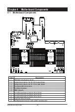
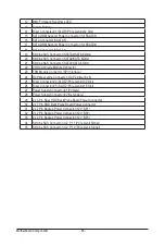
Motherboard Components

- 46 -

12

BMC Firmware Readiness LED

13

System Battery

14

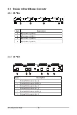
Riser Connector #1 (SLOT1/PCIe Gen4/x32 Slot)

15

SATA DOM Support Power Connector (for SSATA5)

16

SATA Connector (SSATA5)

17

SATA DOM Support Power Connector (for SSATA4)

18

SATA Connector (SSATA4)

19

Slimline SAS Connector (SSATA0/SATA 6Gb/s)

20

Slimline SAS Connector (SATA0/SATA 6Gb/s)

21

Slimline SAS Connector (SATA1/SATA 6Gb/s)

22

VROC Upgrade Module Connector

23

TPM Module Connector (SPI Interface)

24

OCP Mezzanine Connector (OCP 2.0/Gen3 x8)

25

Riser Connector #2 (SLOT2/PCIe Gen4/x32 Slot)

26

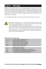
Riser Connector #3 (SLOT2/PCIe Gen4/x16 Slot)

27

Power Supply Connector #1 (Primary)

28

Power Supply Connector #2 (Secondary)

29

2 x 3 Pin Rear HDD Back Plane Board Power Connector

30

2 x 7 Pin HDD Back Plane Board Power Connector

31

2 x 2 Pin Backup Power Connector (12V_BP1)

32

2 x 2 Pin Backup Power Connector (12V_BP2)

33

2 x 2 Pin Backup Power Connector (12V_BP3)

34

Slimline SAS Connector (U2_P1_1/PCIe Gen4 Signal)

35

Slimline SAS Connector (U2_P1_0/PCIe Gen4 Signal)

Summary of Contents for R182-M80

Page 1: ...R182 M80 3rd Gen Intel Xeon Scalable DP Server System 1U 8 Bay Gen4 NVMe User Manual Rev 1 0 ...

Page 2: ... and BIOS User Guide detailed information about the installation use of an add on hardware or software component e g BMC firmware rail kit compatible with this product Quick Installation Guide a short guide with visual diagrams that you can reference easily for installation purposes of this product e g motherboard server barebones Please see the support section of the online product page to check ...

Page 3: ...guide NOTE Gives bits and pieces of additional information related to the current topic CAUTION Gives precautionary measures to avoid possible hardware or software problems WARNING Alerts you to any damage that might result from doing or not doing specific actions ...

Page 4: ... cord extends from the server WARNING To reduce the risk of personal injury from hot surfaces allow the drives and the internal system components to cool before touching them WARNING This server is equipped with high speed fans Keep away from hazardous moving fan blades during servicing WARNING This equipment is intended to be used in Restrict Access Location The access can only be gained by Skill...

Page 5: ...charge ESD and ESD protection ESD can damage drives boards and other parts We recommend that you perform all procedures in this chapter only at an ESD workstation If one is not available provide some ESD protection by wearing an antistatic wrist strap attached to chassis ground any unpainted metal surface on the server when handling parts ESD and handling boards Always handle boards carefully They...

Page 6: ...on if battery is replaced incorrectly or with an incorrect type Replace the battery only with the same or equivalent type recommended by the manufacturer Dispose of used bat teries according to the manufacturer s instructions ...

Page 7: ...26 3 4 Installing the CPU 27 3 5 Installing the Memory 29 3 5 1 Eight Channel Memory Configuration 29 3 5 2 Installing the Memory 30 3 5 3 DIMM Population Table 30 3 5 4 Processor and Memory Module Matrix Table 31 3 5 5 Intel Optane DCPMM DIMM Population Rule 32 3 6 Installing the PCI Expansion Card 33 3 7 Installing the Mezzanine Card 34 3 7 1 OCP 3 0 34 3 7 2 OCP 2 0 35 3 8 Installing the Hard D...

Page 8: ...Connection 69 5 2 13 VLAN Configuration 71 5 2 14 Driver Health 72 5 3 Chipset Menu 73 5 3 1 Processor Configuration 74 5 3 2 Common RefCode Configuration 77 5 3 3 UPI Configuration 78 5 3 4 Memory Configuration 79 5 3 5 IIO Configuration 82 5 3 6 Advanced Power Management Configuration 84 5 3 7 PCH Configuration 86 5 3 8 Miscellaneous Configuration 88 5 3 9 Server ME Configuration 89 5 3 10 Runti...

Page 9: ... 9 5 6 Boot Menu 105 5 7 Save Exit Menu 107 5 8 BIOS POST Beep code AMI standard 109 5 8 1 PEI Beep Codes 109 5 8 2 DXE Beep Codes 109 ...

Page 10: ... 10 This page intentionally left blank ...

Page 11: ... dry and first touch a metal object to eliminate static electricity Prior to installing the motherboard please have it on top of an antistatic pad or within an electrostatic shielding container Before unplugging the power supply cable from the motherboard make sure the power supply has been turned off Before turning on the power make sure the power supply voltage has been set according to the loca...

Page 12: ...Hz LAN 2 x 1Gb s LAN ports Intel I350 AM2 1 x 10 100 1000 management LAN Video Integrated in Aspeed AST2600 2D Video Graphic Adapter with PCIe bus interface 1920x1200 60Hz 32bpp DDR4 SDRAM Storage 4 x 3 5 or 2 5 SATA SAS hot swappable HDD SSD bays 4 x 2 5 7mm SATA NVMe hot swappable HDD SSD bays SAS card is required for SAS devices support RAID Intel SATA RAID 0 1 10 5 Expansion Slot Riser Card CR...

Page 13: ... x LAN activity LEDs 1 x HDD activity LED 1 x System status LED Rear I O 2 x USB 3 0 1 x VGA 2 x RJ45 1 x MLAN 1 x ID button with LED Backplane I O 4 x 3 5 or 2 5 SATA SAS ports 4 x 2 5 SATA NVMe hybrid ports Bandwidth PCIe Gen4 x4 or SATA 6Gb s or SAS 12Gb s per port TPM 1 x TPM header with SPI interface Optional TPM2 0 kit CTM010 Power Supply 1 1 80 PLUS Platinum 1300W redundant PSU AC Input 100...

Page 14: ...r Storage Circular Storage Policy Hardware Inventory Fan Profile System Firewall Power Consumption Power Control LDAP AD RADIUS Support Backup Restore Configuration Remote BIOS BMC CPLD Update Event Log Filter User Management Media Redirection Settings PAM Order Settings SSL Settings SMTP Settings Operating Properties Operating temperature 10 C to 35 C Operating humidity 8 80 non condensing Non op...

Page 15: ...Hardware Installation 15 1 3 System Block Diagram ...

Page 16: ...Hardware Installation 16 This page intentionally left blank ...

Page 17: ...DD0 HDD1 HDD2 HDD3 HDD7 HDD6 HDD5 HDD4 1 2 3 4 No Description 1 Front USB 3 0 Ports 2 Front Panel LEDs and Buttons 3 2 5 HDD Bays 4 3 5 HDD Bays Green HDD Latches Support NVMe Please Go to Chapter 2 3 Front Panel LED and Buttons for detail description of function LEDs ...

Page 18: ... 3 2 1 PSU1 PSU2 5 No Description 1 PCIe Card Slot x 2 2 Mezzanine Card Slot Option OCP 3 0 SFF 3 ID Button with LED 4 10 100 1000 Server Management LAN Port 5 GbE LAN Port x 2 6 USB 3 0 Port x 2 7 Mezzanine Card Slot Option OCP 2 0 8 VGA Port ...

Page 19: ...ive Link LEDs Green Solid On Link between system and network or no access Green Blink Data trasmission or receiving is occuring N A Off No data transmission or receiving is occuring 7 HDD Status LED Green On HDD locate Blink HDD access Amber On HDD fault Green Amber Blink HDD rebuilding N A Off No HDD access or no HDD fault 8 System Status LED Green Solid On System is operating normally Amber Soli...

Page 20: ... Speed LED Yellow On 1 Gbps data rate Green On 100 Mbps data rate N A Off 10 Mbps data rate 2 1GbE Link Activity LED Green On Link between system and network or no access Blink Data transmission or receiving is occurring N A Off No data transmission or receiving is occurring 1 2 1 2 1 2 ...

Page 21: ...een Blinking Power supply firmware updating mode Amber AC cord unplugged or AC power lost with a second power supply in parallel still with AC input power Power supply critical event causing shut down failure OCP OVP fan failure and UVP 1Hz Amber Blinking Power supply warning events where the power supply continues to operate high temp high power high current and slow fan PSU LED ...

Page 22: ...d HDD Access HDD Present No Access BLINK 2 BLINK 2 OFF OFF OFF OFF OFF OFF Low Speed 2 Hz 3 3 Rebuilding HDD Fault OFF OFF ON OFF ON OFF OFF OFF Locate Amber Green ON 1 ON OFF ON 1 OFF Green Amber Green ON 1 Green OFF Amber Amber OFF LED1 LED 2 HDD Present No HDD Green ON OFF NOTE 1 Depends on HBA Utility Spec 2 Blink cycle depends on HDD s activity signal 3 If HDD is pulled out during rebuilding ...

Page 23: ...ou are working inside the computer case If possible wear a grounded wrist strap when you are working inside the computer case Alternatively discharge any static electricity by touching the bare metal system of the computer case or the bare metal body of any other grounded appliance Hold electronic circuit boards by the edges only Do not touch the components on the board unless it is necessary to d...

Page 24: ...er Follow these instructions to remove the chassis cover 1 Remove the screw securing the chassis cover 2 Push button to unlock the handle 3 Pull the grip handle to open the panel cover 4 Slide the cover forward towards the rear of the system and then remove the cover in the direction indicated by the arrow 5 To reinstall the chassis cover reverse steps 1 4 4 1 2 3 ...

Page 25: ...nd Installing the Fan Duct Follow these instructions to remove install the fan duct 1 Lift up to remove the two fan duct 2 To install the fan duct align the fan duct with the guiding groove Push down the fan duct into chassis until its firmly seats ...

Page 26: ...ove the rotating wires into the unlatch position 3 Lift and remove the heat sink from the system 4 To reinstall the heat sink reverse steps 1 3 while ensuring that you tighten the captive screws in sequential order 1g2g3g4 as seen in the image below 1 2 3 4 1 2 3 When installing the heatsink to CPU use T30 Lobe driver to tighten 4 captive nuts in sequence as 1 4 The screw tightening torque 8 0 5 k...

Page 27: ...llow these instructions to install the CPU 1 Align and install the processor on the carrier NOTE Apply thermal compound evenly on the top of the CPU Remove the protective cover from the underside of the heat sink 2 Carefully flip the heatsink cover Then install the carrier assembly on the bottom of the heatsink and make sure the gold arrow is located in the correct direction 3 Remove the CPU cover...

Page 28: ...System Hardware Installation 28 1 2 3 4 6 5 4 ...

Page 29: ... speed and chips be used Always turn off the computer and unplug the power cord from the power outlet before installing the memory to prevent hardware damage Memory modules have a foolproof design A memory module can be installed in only one direction If you are unable to insert the memory switch the direction CPU1 CPU0 DIMM_P0_B0 DIMM_P0_B1 DIMM_P0_A0 DIMM_P0_A1 DIMM_P0_D0 DIMM_P0_D1 DIMM_P0_C0 D...

Page 30: ...the DIMM module 3 Reverse the installation steps when you want to remove the DIMM module 1 2 2 3 5 3 DIMM Population Table Type Ranks Per DIMM and Data Width DIMM Capacity GB Speed MT s Voltage V Slots per Channel SPC and DIMM per Channel DPC 1DPC 2DPC 8Gb 16Gb 1 2V 1 2V RDIMM SRx8 8GB 16GB 3200 3200 RDIMM SRx4 16GB 32GB RDIMM DRx8 16GB 32GB RDIMM DRx4 32GB 64GB RDIMM 3DS 4R 8R x4 2H 64GB 4H 128GB...

Page 31: ... G0 H1 H0 E1 E0 F1 F0 V V V V V V V V V V V V V V V V V V V V V V V V V V V V V V V V V V V V V V V V V V V V V V V V V NOTE l There should be at least one DDR4 DIMM per socket l If only one DIMM is populated in a channel then populate it in the slot furthest away from CPU of that channel l Channel 0 s on each memory controller A E C G I M K O must be populated with same total capacity per channel...

Page 32: ...n slot 0 e g if RDIMM is installed into DIMM slot A0 the DCPMM must be installed into DIMM slot A1 CPU1 CPU0 F0 RDIMM Slot F1 Intel Optane DCPMM Slot E0 RDIMM Slot E1 Intel Optane DCPMM Slot H0 RDIMM Slot H1 Intel Optane DCPMM Slot G0 RDIMM Slot G1 Intel Optane DCPMM Slot K1 Intel Optane DCPMM Slot K0 RDIMM Slot L1 Intel Optane DCPMM Slot L0 RDIMM Slot I1 RIntel Optane DCPMM Slot I0 IRDIMM Slot J1...

Page 33: ...ent The PCIe riser assembly does not include a riser card or any cabling as standard To install a PCIe card a riser card must be installed Follow these instructions for a PCI Expansion card 1 Loosen the thumbscrew securing the riser bracket 2 Lift up the riser bracket out of system 3 Remove the screw securing the slot cover from the riser bracket 4 Remove the slot covers from the riser bracket 5 O...

Page 34: ...s to install an OCP 3 0 mezzanine card 1 Remove the two screws securing the mezzanine card slot cover 2 Remove the slot cover from the system 3 Insert the OCP 3 0 mezzanine card into the card slot ensuring that the card is firmly connected to the connector on the motherboard 4 Tighten the thumbnail screw to secure the OCP 3 0 mezzanine card in place 5 Reverse steps 3 4 to replace the OCP 3 0 mezza...

Page 35: ... card slot cover 4 Remove the slot cover from the system 5 Install the OCP 2 0 slot cover to the system 6 Secure the OCP 2 0 slot cover with the screw 7 Insert the OCP 2 0 mezzanine card into the compartment ensuring that the card is firmly connected to the connector on the motherboard 8 Secure the OCP 2 0 mezzanine card into the system with three screws 9 Reverse the previous steps to replace the...

Page 36: ...ke sure that the hard disk drive is connected to the hard disk drive connector on the backplane Follow these instructions to install a 3 5 Hard Disk Drive 1 Press the release button 2 Extend the locking lever 3 Pull the locking lever in the direction indicated to remove the HDD tray 4 Align the hard disk drive with the positioning stud on the HDD tray 5 Slide the hard disk drive into the HDD tray ...

Page 37: ...ss the release button 2 Extend the locking lever 3 Pull the locking lever in the direction indicated to remove the HDD tray 4 Align the hard disk drive with the positioning screw on the HDD tray 5 Secure the hard disk drive with five screws 6 Reinsert the HDD tray into the slot and close the locking lever 2 1 3 4 5 ...

Page 38: ...he M 2 device The stand off screw is pre installed for 22110 cards as standard Refer to the size of the M 2 device and change the position of the stand off screw accordingly Follow these instructions to install the M 2 device and heat sink 1 Insert the M 2 device into the M 2 connector 2 Press down on the M 2 device 3 Install the thermal pad of the M 2 device to the M 2 device 4 Press down on the ...

Page 39: ...placement fan assembly Voltages can be present within the server whenever an AC power source is connected This voltage is present even when the main power switch is in the off position Ensure that the system is powered down and all power sources have been disconnected from the server prior to replacing a system fan Failure to observe these warnings could result in personal injury or damage to equi...

Page 40: ...supply 1 Press the retaining clip on the right side of the power supply along the direction of the arrow 2 Pull out the power supply handle at the same time and pull out the power supply 3 Insert the replacement power supply firmly into the chassis Connect the AC power cord to the replacement power supply 1 2 3 ...

Page 41: ...System Hardware Installation 41 3 12 Cable Routing Front Switch Cable Front LED Cable Front Panel USB 3 0 Cable ...

Page 42: ...System Hardware Installation 42 HDD Backplane Board Power Cable HDD Backplane Board Signal Cable ...

Page 43: ...System Hardware Installation 43 Motherboard to HDD Back Plane Board Signal Cable SATA0 SATA0 Motherboard to HDD Back Plane Board Signal Cable SATA1 SATA1 ...

Page 44: ...System Hardware Installation 44 U 2 NVMe to HDD Back Plane Board Cable U 2_0 U 2_1 U 2_2 U 2_3 ...

Page 45: ..._GPU3 9 2 x 4 GPU Card Power Connector P12V_GPU1 10 Serial Port Cable Connector 11 OCP Mezzanine Connector OCP 3 0 SFF Type Gen4 x16 CPU1 CPU0 DIMM_P0_B0 DIMM_P0_B1 DIMM_P0_A0 DIMM_P0_A1 DIMM_P0_D0 DIMM_P0_D1 DIMM_P0_C0 DIMM_P0_C1 DIMM_P0_G1 DIMM_P0_G0 DIMM_P0_H1 DIMM_P0_H0 DIMM_P0_E1 DIMM_P0_E0 DIMM_P0_F1 DIMM_P0_F0 DIMM_P1_L1 DIMM_P1_L0 DIMM_P1_K1 DIMM_P1_K0 DIMM_P1_I1 DIMM_P1_I0 DIMM_P1_J1 DIMM...

Page 46: ...rade Module Connector 23 TPM Module Connector SPI Interface 24 OCP Mezzanine Connector OCP 2 0 Gen3 x8 25 Riser Connector 2 SLOT2 PCIe Gen4 x32 Slot 26 Riser Connector 3 SLOT2 PCIe Gen4 x16 Slot 27 Power Supply Connector 1 Primary 28 Power Supply Connector 2 Secondary 29 2 x 3 Pin Rear HDD Back Plane Board Power Connector 30 2 x 7 Pin HDD Back Plane Board Power Connector 31 2 x 2 Pin Backup Power ...

Page 47: ...M_P0_D0 DIMM_P0_D1 DIMM_P0_C0 DIMM_P0_C1 DIMM_P0_G1 DIMM_P0_G0 DIMM_P0_H1 DIMM_P0_H0 DIMM_P0_E1 DIMM_P0_E0 DIMM_P0_F1 DIMM_P0_F0 DIMM_P1_L1 DIMM_P1_L0 DIMM_P1_K1 DIMM_P1_K0 DIMM_P1_I1 DIMM_P1_I0 DIMM_P1_J1 DIMM_P1_J0 DIMM_P1_M0 DIMM_P1_M1 DIMM_P1_N0 DIMM_P1_N1 DIMM_P1_P0 DIMM_P1_P1 DIMM_P1_O0 DIMM_P1_O1 ...

Page 48: ...nnector SATA1 3 SATA Connector SATA2 4 SATA Connector SATA3 Item Description 1 SlimLine SAS Connector U 2_0 2 SlimLine SAS Connector SATA0_1 3 SlimLine SAS Connector U 2_1 4 SlimLine SAS Connector U 2_2 5 SlimLine SAS Connector SATA2_3 6 SlimLine SAS Connector U 2_3 4 3 1 CBP1044 4 3 2 CBP1045 1 2 3 4 1 2 3 4 5 6 ...

Page 49: ... with caution Inadequate BIOS flashing may result in system malfunction It is recommended that you not alter the default settings unless you need to to prevent system instability or other unexpected results Inadequately altering the settings may result in system s failure to boot If this occurs try to clear the CMOS values and reset the board to default values Refer to the Exit section in this cha...

Page 50: ... Change set or disable supervisor and user password Configuration supervisor password allows you to restrict access to the system and BIOS Setup A supervisor password allows you to make changes in BIOS Setup A user password only allows you to view the BIOS settings but not to make changes Boot This setup page provides items for configuration of the boot sequence Save Exit Save all the changes made...

Page 51: ... displayed on the bottom line of the Main Menu Submenu Help While in a submenu press F1 to display a help screen General Help of function keys available for the menu Press Esc to exit the help screen Help for each item is in the Item Help block on the right side of the submenu When the system is not stable as usual select the Restore Defaults item to set your system to its defaults The BIOS Setup ...

Page 52: ...and String Max CPU Speed CPU Signature Processor Core Microcode Patch Displays the technical information for the installed processor s Platform Information Processor PCH RC Revision Displays the platform information of the installed processor s and PCH Memory Information Total Memory Note2 Displays the total memory size of the installed memory Usable Memory Note2 Displays the usable memory size of...

Page 53: ...ion LAN2 MAC Address Note3 Displays LAN MAC address information System Date Sets the date following the weekday month day year format System Time Sets the system time following the hour minute second format Note2 This section will display capacity and frequency information of the memory that the customer has installed Note3 The number of LAN ports listed will depend on the motherboard system model...

Page 54: ...nu options for configuring the function of various hardware components Select a submenu item then press Enter to access the related submenu screen When Boot Mode Select is set to UEFI Default When Boot Mode Select is set to Legacy in the Boot Boot Mode Select section ...

Page 55: ... Description Configuration Security Device Support Enable Disable BIOS support for security device OS will not show security device TCG EFI protocol and INT1A interface will not be available Options available Enable Disable Default setting is Enable ...

Page 56: ...ttings Press Enter to configure advanced items Please note that this item is configurable when COM1 Console Redirection is set to Enabled Terminal Type Selects a terminal type to be used for console redirection Options available VT100 VT100 VT UTF8 ANSI Default setting is VT100 Bits per second Selects the transfer rate for console redirection Options available 9600 19200 38400 57600 115200 Default...

Page 57: ...t setting is 1 Flow Control Flow control can prevent data loss from buffer overflow When sending data if the receiving buffers are full a stop signal can be sent to stop the data flow Once the buffers are empty a start signal can be sent to re start the flow Hardware flow control uses two wires to send start stop signals Options available None Hardware RTS CTS Default setting is None VT UTF8 Combo...

Page 58: ...d Management Windows Emergency Management Services EMS Console Redirection Note EMS console redirection allows the user to configure Console Redirection Settings to support Out of Band Serial Port management Options available Enabled Disabled Default setting is Disabled Serial Port for Out of Band EMS Console Redirection Settings Press Enter to configure advanced items Please note that this item i...

Page 59: ...data loss from buffer overflow When sending data if the receiving buffers are full a stop signal can be sent to stop the data flow Once the buffers are empty a start signal can be sent to re start the flow Hardware flow control uses two wires to send start stop signals Options available None Hardware RTS CTS Software Xon Xoff Default setting is None ...

Page 60: ...to Enabled allows you to configure the serial port settings When set to Disabled displays no configuration for the serial port Options available Enabled Disabled Default setting is Enabled Current Displays the serial port base I O address and IRQ Possible Configures the serial port base I O address and IRQ Use Automatic Settings IO 3F8h IRQ 4 DMA IO 3F8h IRQ 4 DMA IO 2F8h IRQ 4 DMA IO 3E8h IRQ 4 D...

Page 61: ...board LAN1 LAN2 I O ROM Note2 Enable Disable the onboard LAN1 LAN2 devices and initializes device expansion ROM Options available Enabled Disabled Default setting is Enabled PCI Devices Common Settings Above 4G Decoding Enable Disable memory mapped I O to 4GB or greater address space Above 4G Decoding Options available Enabled Disabled Default setting is Enabled SR IOV Support If the system has SR...

Page 62: ...and off support Options available Enabled Disabled Default setting is Enabled USB Mass Storage Driver Support Note Enable Disable the USB Mass Storage Driver Support Options available Enabled Disabled Default setting is Enabled Port 60 64 Emulation Enables the I O port 60h 64h emulation support This should be enabled for the complete USB Keyboard Legacy support for non USB aware OS Options availab...

Page 63: ...ions available Enabled Disabled Default setting is Disabled Ipv6 PXE Support Enable Disable the Ipv6 PXE feature Options available Enabled Disabled Default setting is Enabled Ipv6 HTTP Support Enable Disable the Ipv6 HTTP feature Options available Enabled Disabled Default setting is Disabled PXE boot wait time Wait time in seconds to press ESC key to abort the PXE boot Press the keys to increase o...

Page 64: ... Post Report Configuration Parameter Description Post Report Configuration Error Message Report Post Error Message Enable Disable the POST Error Message support Options available Enabled Disabled Default setting is Enabled ...

Page 65: ...up 5 2 8 NVMe Configuration Parameter Description NVMe Configuration Displays the NVMe devices connected to the system NVMe OPROM Select Options available BIOS Build In NVMe Device Default setting is BIOS Build In ...

Page 66: ... VGA Enable Disable 64bit capable devices to be decoded in Skip Above 4G Address VGA Space Options available Enabled Disabled Default setting is Disabled P2P Bridge IO Size Specifies P2P Bridge IO aligned to the size Options available 0x100 0x150 0x1000 Default setting is 0x1000 SATA HDD Security Frozen Enable Disable this item to send freeze lock command to SATA HHD Options available Enabled Disa...

Page 67: ...figuration of advanced items Enroll Cert Press Enter to enroll a certificate Enroll Cert Using File Cert GUID Input digit character in 1111111 2222 3333 4444 1234567890ab format Commit Changes and Exit Discard Changes and Exit Delete Cert Client Cert Configuration Press Enter for configuration of advanced items ...

Page 68: ... items Attempt Priority Options available Host Attempt Redfish Attempt Default setting is Host Attempt Commit Changes and Exit Host iSCSI Configuration Press Enter to configure advanced items iSCSI Initiator Name Only IQN format is accepted Range from 4 to 223 Add an Attempt Delete Attempts Change Attempt Order ...

Page 69: ... 69 BIOS Setup 5 2 12 Intel R i350 Gigabit Network Connection ...

Page 70: ...he numeric keys to adjust desired values up to 15 seconds UEFI Driver Displays the technical specifications for the Network Interface Controller Adapter PBA Displays the technical specifications for the Network Interface Controller Device Name Displays the technical specifications for the Network Interface Controller Chip Type Displays the technical specifications for the Network Interface Control...

Page 71: ...ng VLAN Press the keys to increase or decrease the desired values The valid range is from 0 to 4094 Priority Sets 802 1Q Priority for a new VLAN or an existing VLAN Press the keys to increase or decrease the desired values The valid range is from 0 to 7 Add VLAN Press Enter to create a new VLAN or update an existing VLAN Configured VLAN List Remove VLAN Press Enter to remove an existing VLAN ...

Page 72: ... 72 BIOS Setup 5 2 14 Driver Health Parameter Description Driver Health Displays driver health status of the devices controllers if installed ...

Page 73: ...IOS Setup 5 3 Chipset Menu Chipset Setup menu displays submenu options for configuring the function of Platform Controller Hub PCH Select a submenu item then press Enter to access the related submenu screen ...

Page 74: ... 74 BIOS Setup 5 3 1 Processor Configuration ...

Page 75: ...ble Default setting is Disable L2 RF0 Prefetch Disable Options available Enable Disable Default setting is Disable Adjacent Cache Prefetch When enabled cache lines are fetched in pairs When disabled only the required cache line is fetched Options available Enable Disable Default setting is Enable DCU Streamer Prefetcher Enable Disable DCU streamer prefetcher Options available Enable Disable Defaul...

Page 76: ...ter Description Debug Consent Options available Enable Disable Default setting is Disable Total Memory Encryption TME Enable Disable total memory encryption TME Options available Enabled Disabled Default setting is Disabled ...

Page 77: ...k is the default allocation Options available 1G 4G 16G 64G 256G 1024G Default setting is 256G Isoc Mode Enable Disable the Isochronous support in order to meet the QoS requirements Quality of Service Options available Auto Enable Disable Default setting is Auto Numa Non Uniform Memory Access Enable Disable Non uniform Memory Access NUMA support to improve the system performance Options available ...

Page 78: ...s available 9 6GT s 10 4GT s 11 2GT s Auto Default setting is Auto SNC Sub NUMA Enable Disable Sub NUMA Cluster function Options available Disable Enable SNC2 2 clusters Default setting is Disable Stale AtoS Enable Disable Stale A to S directory optimization Options available Disable Enable Auto Default setting is Auto LLC dead line alloc Enable Disable fill dead lines in LLC Options available Dis...

Page 79: ...ng is Auto Enable ADR Enables the detecting and enabling of ADR Asynchronous DRAM Refresh function Options available Enable Disable Default setting is Enable Legacy ADR Mode Enable Disable the Legacy ADR Mode Options available Enable Disable Default setting is Disable Minimum System Memory Size Configures the minimum memory size Options available 2GB 4GB 6GB 8GB Default setting is 2GB ADR Data Sav...

Page 80: ...ype Displays the RAS type New SDDC Mode Enable Disable 48B SDDC ECC from ICX C0 Onwards Options available Disabled Enabled Default setting is Enabled Mirror Mode Mirror Mode will set entire 1LM memory in system to be mirrored consequently reducing the memory capacity by half Enables the Mirror Mode will disable the XPT Prefetch Options available Disabled Full Mirror Mode Partial Mirror Mode Defaul...

Page 81: ... decrease the desired values Leaky bucket high bit Configures leaky bucket high bit 1 63 Press the keys to increase or decrease the desired values ADDDC Sparing Enable Disable ADDDC Sparing Options available Disabled Enabled Default setting is Disabled Column Correction Disable Options available Disable Enable Default setting is Disable Set PMem Die Sparing Options available Disabled Enabled Defau...

Page 82: ...S only to Chipset PCIe Root Ports Bridges Disable Programs ACS to all PCIe bridges Default setting is Enable DMA Control Opt In Flag Enable Disable DMA_CTRL_PLATFORM_OPT_IN_FLAG in DMAR table in ACPI Not compatible with Direct Device Assignment DDA Options available Enable Disable Default setting is Disable Interrupt Remapping Enable Disable the interrupt remapping support function Options availab...

Page 83: ...guration Enable Disable Intel VMD technology Options available Enable Disable Default setting is Disable Intel VMD for Non Hotplug NVMe Note Enable Disable Intel VMD for Non Hotplug NVMe Options available Enable Disable Default setting is Disable Note This item appears when Intel VMD Configuration is set to Enable ...

Page 84: ...nable Activate SST BF Enable Disable SST BF Options available Enable Disable Default setting is Disable Configure SST BF Note Enable Disable BIOS to configure SST BF High Priority Cores Options available Enable Disable Default setting is Enable Turbo Mode When this item is enabled the processor will automatically ramp up the clock speed of 1 2 of its processing cores to improve its performance Whe...

Page 85: ... CPU C6 ACPI C3 report to OS Options available Disable Enable Auto Default setting is Disable Enhanced Halt State C1E Core C1E auto promotion control Takes effect after reboot Options available Enable Disable Default setting is Disable Package C State Control Press Enter to configure advanced items Package C State Configures the state for the C State package limit Options available C0 C1 state C2 ...

Page 86: ...sabled and cannot be access the RAID setup utility at boot time RAID Mode When set to RAID the SATA controller enables both its RAID and AHCI functions You will be allowed to access the RAID setup utility at boot time Options available AHCI RAID Default setting is AHCI Alternate Device ID on RAID Note 1 Enable Disable Alternate Device ID on RAID mode Options available Enable Disable Default settin...

Page 87: ...utility at boot time RAID Mode When set to RAID the SATA controller enables both its RAID and AHCI functions You will be allowed to access the RAID setup utility at boot time Options available AHCI RAID Default setting is AHCI Alternate Device ID on RAID Note 1 Enable Disable Alternate Device ID on RAID mode Options available Enable Disable Default setting is Disabled sSATA Port 0 1 2 3 4 5 The ca...

Page 88: ...3 8 Miscellaneous Configuration Parameter Description Miscellaneous Configuration Active Video Selects the active video type Options available Auto Onboard Device PCIE Device Specific PCIE Device Default setting is Auto ...

Page 89: ...plays ME Firmware status information Current State Displays ME Firmware current status information Error Code Displays ME Firmware status error code Recovery Cause Displays ME Firmware recovery cause PTT Support Displays if the system supports the Intel Platform Trust Technology Suppress PTT Commands Displays if the system supports to Bypass TPM2 commands submitting to PTT Firmware ...

Page 90: ...onfigure advanced items WHEA Windows Hardware Error Architecture Support Enable Disable WHEA Support Options available Enable Disable Default setting is Enable Memory Error Enabling Press Enter to configure advanced items Memory Error Enable Disable Memory Error Options available Enable Disable Default setting is Enable Memory Corrected Error Enable Disable Memory Corrected Error Options available...

Page 91: ... 91 BIOS Setup Parameter Description PCIe Error Enabling Press Enter to configure advanced items PCIE Error Enable Disable PCIE error Options available Enable Disable Default setting is Disable ...

Page 92: ...mp up the clock speed of 1 2 of its processing cores to improve its performance When this item is disabled the processor will not overclock any of its core Options available Enabled Disabled Default setting is Enabled CPU C6 report Enable Disable the BIOS to enable the report from the CPU C6 state ACPI C3 to the OS Options available Disabled Enabled Auto Default setting is Disabled Enhanced Halt S...

Page 93: ...s available Enabled Disabled Default setting is Enabled DCU Streamer Prefetcher Options available Enabled Disabled Default setting is Enabled Isoc Mode Enable Disable the Isochronous support in order to meet the QoS requirements Quality of Service Options available Auto Enabled Disabled Default setting is Auto Intel VT for Directed I O VT d Enable Disable the Intel VT for Directed I O VT d support...

Page 94: ...og Timer Enable Disable OS Watchdog Timer function Options available Enabled Disabled Default setting is Disabled OS Wtd Timer Timeout Note2 Configures OS Watchdog Timer The value is between 1 to 30 minutes Default setting is 10 minutes OS Wtd Timer Policy Note2 Configure OS Watchdog Timer Policy Options available Reset Do Nothing Power Down Power Cycle Default setting is Reset Wait BMC Ready POST...

Page 95: ...re advanced items View FRU Information Press Enter to view the FRU information BMC VLAN Configuration Press Enter to configure advanced items BMC network Configuration Press Enter to configure advanced items IPv6 BMC Network Configuration Press Enter to configure advanced items ...

Page 96: ...ose options for erasing SEL Options available No Yes On next reset Yes On every reset Default setting is No When SEL is Full Choose options for reactions to a full SEL Options available Do Nothing Erase Immediately Delete Oldest Record Default setting is Do Nothing Custom EFI Logging Options Log EFI Status Codes Enable Disable the logging of EFI Status Codes if not already converted to legacy Opti...

Page 97: ...U Information The FRU page is a simple display page for basic system ID information as well as System product information Items on this window are non configurable Note The model name will vary depends on the product you purchased ...

Page 98: ...uration BMC VLAN ID Select to configure BMC VLAN ID The valid range is from 0 to 4094 When set to 0 BMC VLAN ID will be disabled BMC VLAN Priority Select to configure BMC VLAN Priority The valid range is from 0 to 7 When BMC VLAN ID is set to 0 BMC VLAN Priority will not be selected ...

Page 99: ...ilable Unspecified Static DynamicBmcDhcp Default setting is DynamicBmcDhcp Station IP address Displays IP Address information Subnet mask Displays Subnet Mask information Please note that the IP address must be in three digitals for example 192 168 000 001 Router IP address Displays the Router IP Address information Station MAC address Displays the MAC Address information Real time get BMC network...

Page 100: ...twork during BIOS phase Options available Unspecified Disable Enable Default setting is Enable IPv6 BMC Lan IP Address Source Selects to configure LAN channel parameters statically or dynamically by BIOS or BMC Options available Unspecified Static Dynamic Obtained by BMC running DHCP Default setting is Enable Dynamic Obtained by BMC running DHCP IPv6 BMC Lan IP Address Prefix Length Check if the I...

Page 101: ...all settings in the Setup Utility User Password Entering this password will restrict a user s access to the Setup menus To enable or disable this field a Administrator Password must first be set A user can only access and modify the System Time System Date and Set User Password fields Parameter Description Administrator Password Press Enter to configure the administrator password User Password Pre...

Page 102: ... the applications that are running during the booting process to be pre signed with valid digital certificates This way the system knows all files being loaded before Windows loads to the login screen have not been tampered with When set to Standard it will automatically load the Secure Boot keys form the BIOS databases When set to Custom you can customize the Secure Boot settings and manually loa...

Page 103: ...ce Guard Ready Remove UEFI CA from DB Press Enter to remove Microsoft UEFI CA from Secure Boot DB Restore DB defaults Restore DB variable to factory defaults Secure Boot variable Displays the current status of the variables used for secure boot Platform Key PK Displays the current status of the Platform Key PK Press Enter to configure a new PK Options available Update Key Exchange Keys KEK Display...

Page 104: ...tabase Press Enter to configure a new DBT or load additional DBT from storage devices Options available Update Append OsRecovery Signatures Displays the current status of the OsRecovery Signature Database Press Enter to configure a new OsRecovery Signature or load additional OsRecovery Signature from storage devices Options available Update Append ...

Page 105: ...sired values Bootup NumLock State Enable Disable the Bootup NumLock function Options available On Off Default setting is On Quiet Boot Enable Disable showing the logo during POST Options available Enabled Disabled Default setting is Enabled Setup Flash Press Enter to run setup flash Dump full Setup Data Press Enter to dump full setup data to file Dump non default Setup Data Press Enter to dump non...

Page 106: ... the boot order priority By default the server searches for boot devices in the following sequence 1 Hard drive 2 CD COM DVD drive 3 USB device 4 Network 5 UEFI UEFI Network Drive BBS Priorities Press Enter to configure the boot priority UEFI Application Boot Priorities Press Enter to configure the boot priority ...

Page 107: ... Discard Changes and Exit Discards changes made and exits the BIOS setup Options available Yes No Save Changes and Reset Restarts the system after saving the changes made Options available Yes No Discard Changes and Reset Restarts the system without saving any changes Options available Yes No Save Changes Saves changes done so far to any of the setup options Options available Yes No Discard Change...

Page 108: ...ese settings the system might not function properly Options available Yes No Save as User Defaults Saves the changes made as the user default settings Options available Yes No Restore User Defaults Loads the user default settings for all BIOS setup parameters Options available Yes No Boot Override Press Enter to configure the device as the boot up drive Launch EFI Shell from filesystem device Atte...

Page 109: ... Recovery failed 4 S3 Resume failed 7 Reset PPI is not available of Beeps Description 1 Invalid password 4 Some of the Architectural Protocols are not available 5 No Console Output Devices are found 5 No Console Input Devices are found 6 Flash update is failed 7 Reset protocol is not available 8 Platform PCI resource requirements cannot be met 5 8 BIOS POST Beep code AMI standard 5 8 1 PEI Beep Co...

Reviews: