- 82 -
BIOS Setup
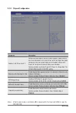
Parameter
Description
Restore NVDIMMs
Enable/Disable Automatic restoring of NVDIMMs.
Options available: Enable, Disable. Default setting is
Enable
.
Interleave NVDIMMs
Controls if NVDIMMs are interleaved together or not.
Options available: Enable, Disable. Default setting is
Enable
.
Assert ADR on Reset
Enable/Disable Assert ADR on Reset.
Options available: Enabled, Disabled. Default setting is
Disabled
.
Assert ADR on S5
Enable/Disable Assert ADR on S5.
Options available: Enabled, Disabled. Default setting is
Disabled
.
Get Memory Timing
Auto is the detected SPD value and use it, otherwise use BIOS Build-in.
Options available: Auto, BIOS Build-in. Default setting is
BIOS Build-in
.
Memory Topology
Press [Enter] to view memory topology with DIMM population
information.
Memory RAS Configuration
Press [Enter] to configure advanced items.
RAS Type
– Displays the RAS type.
New SDDC Mode
– Enable/Disable 48B SDDC ECC from ICX C0 Onwards.
– Options available: Disabled, Enabled. Default setting is
Enabled
.
Mirror Mode
– Mirror Mode will set entire 1LM memory in system to be
mirrored, consequently reducing the memory capacity by half.
Enables the Mirror Mode will disable the XPT Prefetch.
– Options available: Disabled, Full Mirror Mode, Partial Mirror
Mode. Default setting is
Disabled
.
Correctable Error Threshold
– Correctable Error Threshold (0x01-0x7fff) used for sparing, and
leaky bucket.
– Press the <+> / <-> keys to increase or decrease the desired
values.
Trigger SW Error Threshold
– Enable/Disable Sparing trigger SW Error Match Threshold.
– Options available: Disabled, Enabled. Default setting is
Disabled
.
Sparing SW Error Match Threshold
– Correctable Error Threshold (1-32767) used for bank level
information.
– Press the <+> / <-> keys to increase or decrease the desired
values.
Correctable Error Time Window
– Correctable Error time window based interface in hour (0-24).
– Press the <+> / <-> keys to increase or decrease the desired
values.
Summary of Contents for R182-N20
Page 10: ... 10 This page intentionally left blank ...
Page 16: ...Hardware Installation 16 1 3 System Block Diagram 1 3 1 R182 N20 ...
Page 17: ... 17 Hardware Installation 1 3 2 R182 NA0 ...
Page 18: ...Hardware Installation 18 This page intentionally left blank ...
Page 25: ...System Appearance 25 This page intentionally left blank ...
Page 49: ...System Hardware Installation 46 This page intentionally left blank ...
Page 74: ... 71 BIOS Setup 5 2 12 Intel R i350 Gigabit Network Connection ...
Page 79: ... 76 BIOS Setup 5 3 1 Processor Configuration ...


