


- 19 -
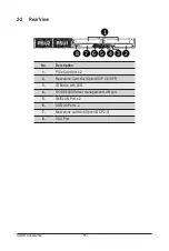
System Appearance
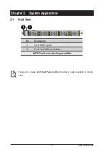
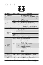
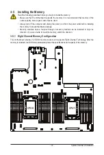
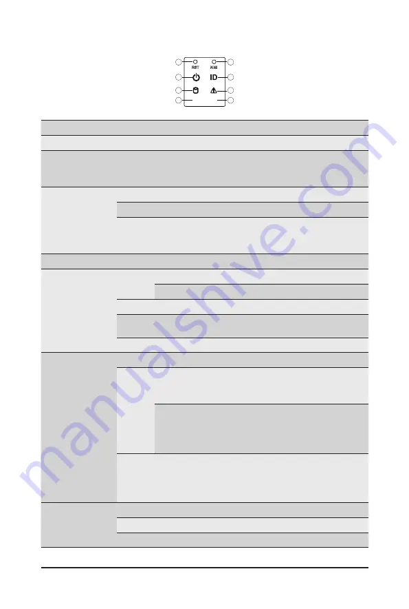
2-3 Front Panel LEDs and Buttons
L1
L2
2
4
6
8
1
3
5
7
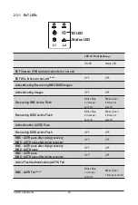
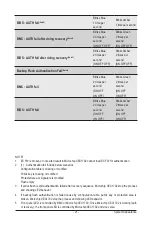
(Note) If your server features RoT function, please see the following section for detail LED behavior.
No. Name
Color
Status
Description
1.
Reset Button
Press the button to reset the system.
2.
NMI button
Press the button server generates a NMI to the processor
if the multiple-bit ECC errors occur, which effectively halt
the server.
3.
Power button
with LED
Green
On
System is powered on
Green
Blink
System is in ACPI S1 state (sleep mode)
N/A
Off
•
System is not powered on or in ACPI S5 state
(power off)
•
System is in ACPI S4 state (hibernate mode)
4.
ID Button
(Note)
Press the button to activate system identification
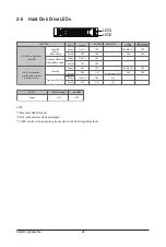
5.
HDD Status
LED
Green
On
HDD locate
Blink
HDD access
Amber
On
HDD fault
Green/
Amber
Blink
HDD rebuilding
N/A
Off
No HDD access or no HDD fault.
6.
System
Status
LED
(Note)
Green
Solid On System is operating normally.
Amber
Solid On
Critical condition, may indicate:
System fan failure
System temperature
Blink
Non-critical condition, may indicate:
Redundant power module failure
Temperature and voltage issue
Chassis intrusion
N/A
Off
System is not ready, may indicate:
POST error
NMI error
Processor or terminator missing
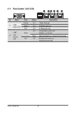
7/8.
LAN 1/2
Active/Link
LEDs
Green
Solid On Link between system and network or no access.
Green
Blink
Data trasmission or receiving is occuring
N/A
Off
No data transmission or receiving is occuring
Summary of Contents for R182-Z93
Page 1: ...R182 Z93 AMD EPYC 7003 DP Server System 1U 10 Bay Gen4 NVMe User Manual Rev 1 0 ...
Page 10: ... 10 This page left intentionally blankThis ...
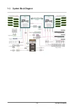
Page 16: ... 16 Hardware Installation 1 3 System Block Diagram ...
Page 42: ...System Hardware Installation 42 NVMe Card 4 5 NVMe Card 6 7 Top Bo om Bo om Top R182 Z92 ...
Page 43: ... 43 System Hardware Installation NVMe Card 8 9 HDD Backplane Board Signal R182 Z92 ...
Page 44: ...System Hardware Installation 44 HDD Backplane Board Power Front Panel IO R182 Z92 ...
Page 45: ... 45 System Hardware Installation Front Panel USB ...
Page 46: ...System Hardware Installation 46 This page intentionally left blank ...
Page 50: ...Motherboard Components 50 This page left intentionally blankThis ...
Page 56: ...BIOS Setup 66 When Boot Mode Select is set to Legacy in the Boot Boot Mode Select section ...
Page 61: ... 71 BIOS Setup 5 2 4 1 Serial Port 1 2 Configuration ...
Page 69: ... 79 BIOS Setup 5 2 8 PCI Subsystem Settings ...
Page 80: ...BIOS Setup 90 5 2 17 Intel R I350 Gigabit Network Connection ...
Page 144: ...BIOS Setup 154 This page intentionally left blank ...


