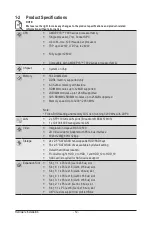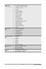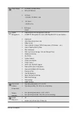
- 17 -
System Appearance
Chapter 2 System Appearance
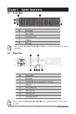
2-1 Front View
No.
Description
1.
Power Button
2.
Front Panel LEDs
3.
ID Button
4.
HDD bays
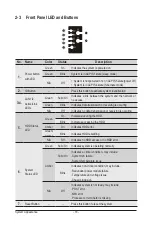
• Refer to Chapter
2-3 Front Panel LED
and Buttons for a detailed description of the function
of the LEDs.
4
1
2
3
HDD #0
HDD #1
HDD #2
HDD #3
HDD #4
HDD #5
HDD #6
HDD #7
HDD #8
HDD #9
HDD #10
HDD #1
1
HDD #12
HDD #13
HDD #14
HDD #15
HDD #16
HDD #17
HDD #18
HDD #19
HDD #20
HDD #21
HDD #22
HDD #23
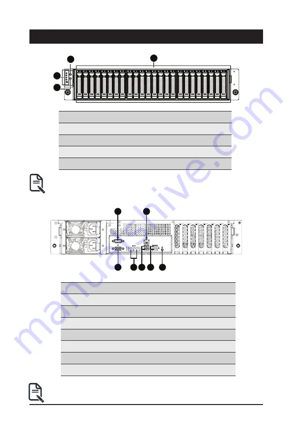
2-2 Rear View
No.
Description
1.
Serial port
2.
10/100/1000 Server management LAN port
3.
VGA port
4.
SFP+ LAN ports
5.
USB 3.0 ports
6.
USB 2.0 ports
7.
ID button with LED
3
2
5 6
7
1
4
Primary
PSU
Secondary
PSU
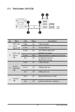
• Refer to Chapter
2-4 Rear System LAN LEDs
for a detailed description of the function of
the LEDs.
4
1
2
3
HDD #0
HDD #1
HDD #2
HDD #3
HDD #4
HDD #5
HDD #6
HDD #7
HDD #8
HDD #9
HDD #10
HDD #1
1
HDD #12
HDD #13
HDD #14
HDD #15
HDD #16
HDD #17
HDD #18
HDD #19
HDD #20
HDD #21
HDD #22
HDD #23
3
2
5 6
7
1
4
Primary
PSU
Secondary
PSU
Summary of Contents for R271-Z31
Page 1: ...R271 Z31 AMD EPYC 7003 UP Server System 2U 16 Bay User Manual Rev 1 0 ...
Page 10: ... 10 This page intentionally left blank ...
Page 16: ...Hardware Installation 16 This page intentionally left blank ...
Page 22: ...System Appearance 22 This page intentionally left blank ...
Page 27: ... 27 System Hardware Installation 6 7 4 1 3 2 5 ...
Page 40: ...Motherboard Components 40 This page intentionally left blank ...
Page 46: ...BIOS Setup 46 When Boot Mode Select is set to Legacy in the Boot Boot Mode Select section ...
Page 59: ... 41 BIOS Setup 5 2 8 PCI Subsystem Settings ...
Page 70: ...BIOS Setup 70 5 2 17 QLogic 577xx 578xx 10 Gb Ethernet ...
Page 72: ...BIOS Setup 72 5 2 17 1 Firmware Image Menu ...
Page 139: ... 41 BIOS Setup This page intentionally left blank ...

