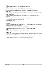
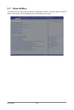


BIOS Setup
- 68 -
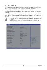
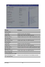
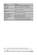
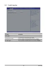
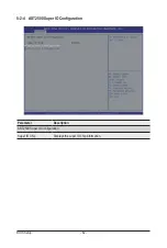
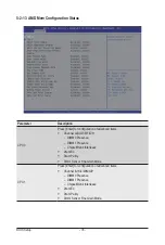
5-2-7
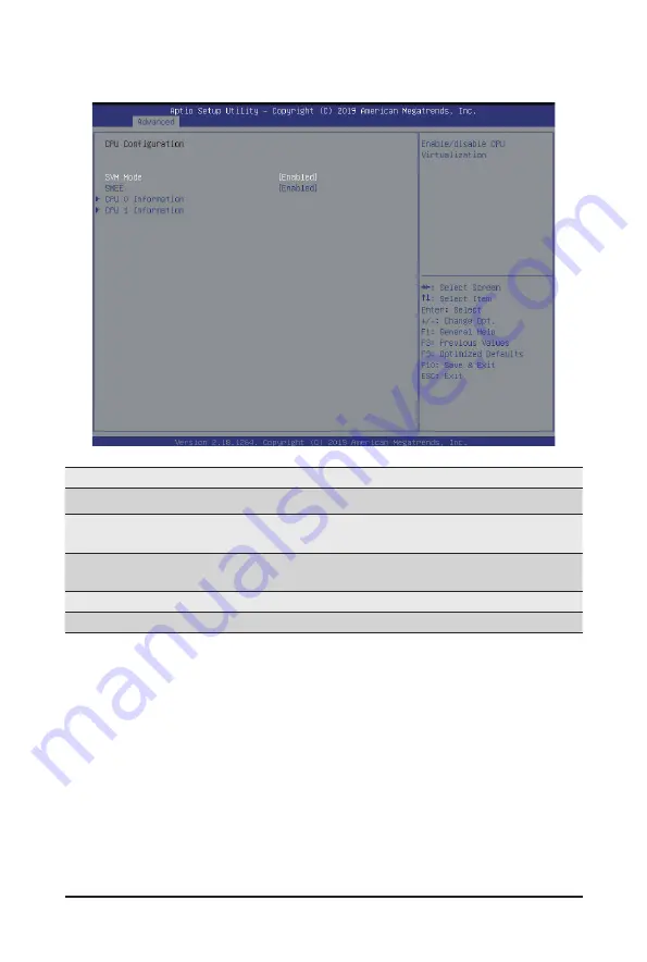
CPU Configuration
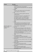
Parameter
Description
CPU Configuration
SVM Mode
Enable/disable the CPU Virtualization.
Options available: Enabled/Disabled. Default setting is
Enabled
.
SMEE
Controls the Secure Memory Encryption Enable (SMEE) function.
Options available: Enabled/Disabled. Default setting is
Enabled
.
CPU 0 Information
Press [Enter] to view more information related to CPU 0.
CPU 1 Information
Press [Enter] to view more information related to CPU 1.
Summary of Contents for R282-Z96
Page 1: ...R282 Z96 AMD EPYC 7002 DP Server System 2U 12 Bay GPU NVMe sku User Manual Rev 1 0 ...
Page 10: ... 10 This page intentionally left blank ...
Page 14: ...Hardware Installation 14 ...
Page 16: ...Hardware Installation 16 1 3 System Block Diagram ...
Page 24: ...System Appearance 24 This page intentionally left blank ...
Page 35: ... 35 System Hardware Installation 4 5 6 7 4 5 6 7 5 6 6 7 7 9 4 ...
Page 39: ... 39 System Hardware Installation 5 Push Push 6 ...
Page 43: ... 43 System Hardware Installation Onboard SATA Cable Onboard SATA Cable 3 12 Cable Routing ...
Page 46: ...System Hardware Installation 46 GPU Card Power Cable ...
Page 47: ... 47 System Hardware Installation NVMe Card Cable CNV3134 U2_A U2_8 CNV3134 U2_B U2_9 ...
Page 48: ...System Hardware Installation 48 NVMe Card Cable CNV3134 U2_C U2_10 CNV3134 U2_D U2_11 ...
Page 52: ...Motherboard Components 52 This page intentionally left blank ...
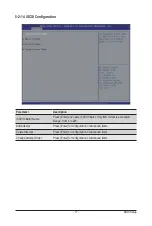
Page 74: ...BIOS Setup 74 5 2 11 SATA Configuration ...
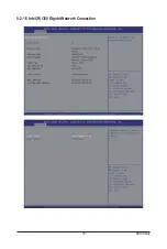
Page 79: ... 79 BIOS Setup 5 2 16 Intel R I350 Gigabit Network Connection ...


