1 - 8 System Map: LCD Panel Open - Model A Design II
Quick Start Guide
1
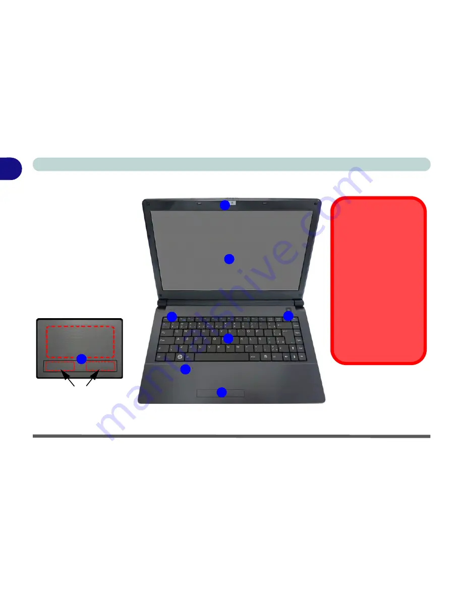
System Map: LCD Panel Open - Model A Design II
Figure 1 - 3
LCD Panel Open -
Model A Design II
1.
Built-in PC Camera
(
Optional
)
2.
LCD
3.
Power Button
4.
LED Status
Indicators
5.
Keyboard
6.
Built-In Microphone
7.
Touchpad &
Buttons
7
Touchpad Buttons
(valid operation area)
2
4
1
6
7
3
5
Wireless Device
Operation Aboard
Aircraft
The use of any portable electronic
transmission devices aboard air-
craft is usually prohibited. Make
sure the module(s) are OFF if you
are using the computer aboard
aircraft.
Use the key combinations to tog-
gle power to the
3.75G/HSPA/
WLAN/Bluetooth
modules, and
check the LED indicator or on-
screen icon to see if the modules
are powered on or not (see
Table 1 - 6, on page 1 - 18
/
Table 1 - 2, on page 1 - 12
).
Note that the Touchpad and Buttons valid operational area is that indicated within the red dotted lines
indicated on the right.
Summary of Contents for W270BUQ
Page 1: ...V11 2 00 ...
Page 2: ......
Page 24: ...XXII Preface ...
Page 54: ...Quick Start Guide 1 30 1 ...
Page 68: ...Features Components 2 14 2 ...
Page 127: ...Modules Options PC Camera Module 7 5 7 Figure 7 1 Audio Setup for PC Camera Right click ...
Page 196: ...Modules Options 7 74 7 ...
Page 216: ...Interface Ports Jacks A 4 A ...
Page 236: ...AMD Video Driver Controls B 20 B ...
Page 242: ...Specifications C 6 C ...


