5
Installation
GGF-400, GGF-720
This section summarizes procedures necessary for proper installation of the
GGF Series Gas Fryer
. To prevent personal
injury or damage to the equipment, please ensure the following steps are taken and the following check sheet is
initialed and dated.
INSTALLATION CHECK SHEET
Check
Date
Initial
Section
Description
X
8/18/05
CSY
0.0
Completely read Manual (EXAMPLE)
2-01.
Inspect crate for damage
2-01.
Uncrate
2-02.
Proper clearances
2-04.
Proper ventilation
2-05.
Proper circuit breaker installed (Licensed Electrician Only)
2-06.
Proper electrical connections (Licensed Electrician Only)
2-07.
Unit has power (Licensed Electrician Only)
2-08.
Gas line connected (Qualified Gas Technician Only)
2-09.
Correct gas orifice installed (Qualified Gas Technician Only)
2-10.
Correct gas pressure setting (Qualified Gas Technician Only)
2-11.
Correct blower vacuum switch setting (Qualified Gas Technician Only)
2-12.
Filter Pump operating
2-13.
Restraint device installed
2-14.
Performed Boil-Out procedure
2-15.
Cleaned Filter Pan
Various installation tasks described in this Manual
MUST
be performed only by a Licensed Electrician and a
Qualified Gas Appliance Technician.
NOTE:
This appliance must be electrically grounded in accordance with the local codes, or in the absence of local codes,
with the
National Electrical Code, ANSI/NFPA 70
, or
Canadian Electrical code, CSA C22.2
, as applicable.
2.
Installation
2.1.
Appliance Location
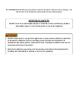
DO NOT MODIFY, ADD ATTACHMENTS OR OTHERWISE ALTER THIS EQUIPMENT.
DO NOT install or use the appliance in a location or kitchen space that does not have ventilation to
the outside. Ventilation must be sufficient to provide a adequate fresh air exchange rate to prevent accummulation of
hazardous combustion gases (carbon monoxide & CO2). Failure to comply can result in personal injury, even death.
Continued on Next Page
Summary of Contents for GGF Series
Page 13: ...4 Model GGF 400 GGF 720 Introduction ...
Page 26: ...Model GGF 400 GGF 720 Overview 18 3 1 Control Panel 5 6 4 3 2 1 7 ...
Page 28: ...20 Model GGF 400 GGF 720 Overview 3 2 Lower Cabinet 5 6 4 3 2 1 7 ...
Page 32: ...24 Model GGF 400 GGF 720 Overview 3 4 Basket and Elevator Assembly 3 1 2 4 ...
Page 38: ...30 Model GGF 400 GGF 720 Overview Notes ...
Page 42: ...34 Fryer Preparation Model GGF 400 GGF 720 ...
Page 80: ...72 Troubleshooting Model GGF 400 GGF 720 ...
Page 88: ...80 Parts List 8 5 Plumbing Model GGF 400 GGF 720 1 2 2 3 3 4 5 6 7 7 7 7 8 10 11 9 12 ...
Page 90: ...82 Parts List 8 6 Basket Basket Cover Model GGF 400 GGF 720 1 2 3 ...
Page 94: ...86 Parts List Notes Model GGF 400 GGF 720 ...
Page 95: ......


