14
Installation
GGF-400, GGF-720
2.10.
Blower Vacuum Switch Setting & Adjustment
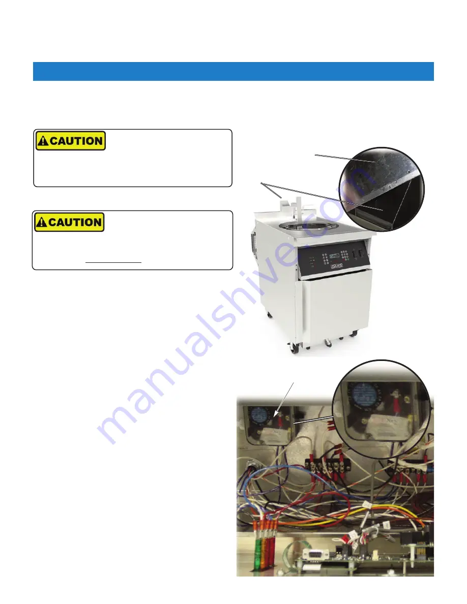
The Blower Vacuum Switch ensures that the unit has proper draft air-flow before allowing the gas valve to open for
ignition. The switch has been factory set, but differences in conditions at the installation site may affect the setting.
Use the following steps to confirm that the Blower Vacuum Switch is adjusted properly for local conditions.
DO NOT EVER check or adjust the Blower Vacuum
Switch without having fry pot filled with water, or
cooking oil.
1. Fryer should remain
ON
and continue heating water
from the previous procedure.
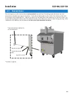
2. While the burner(s) are
ON, u
se a piece of
non-
combustible material
to diagonally block, from
corner to corner, about half of the flue stack opening.
3. The burner(s) and the draft fan should shutdown.
When the opening is unblocked, the fan should
restart and burner(s) should relight. If this occurs,
the setting is satisfactory, go to
Step-8
.
If burner(s) fail to shutdown, the Blower Vacuum
Switch must be adjusted as follows:
4. Shutdown Fryer.
5. Remove retaining screws at the top of the Control
Panel and lower panel.
6. Locate pressure switch on left side of the Control
Box; remove plastic cover, if still in place.
7. Slowly rotate the pressure switch adjustment dial to
the right (clockwise) to increase sensitivity ... to the
left (counter-clockwise) decreases. Restart Fryer and
repeat
Step-2 thru 3
. As necessary, continue
incremental adjustments until the burner(s)
consistently shutdown when approx. half of the stack
opening is blocked.
Shutdown Fryer and secure Control Panel.
8. Drain water from the Fry Pot into a suitable container
(NOT Filter Pan)
. Proceed to
Section 2-12
.
During the next steps use great caution and wear
thermal hand protection. The air exhausted from the
flue stack is EXTREMELY HOT!!
Non-Combustible
Material
Flue Stack
Vacuum Switch
Summary of Contents for GGF Series
Page 13: ...4 Model GGF 400 GGF 720 Introduction ...
Page 26: ...Model GGF 400 GGF 720 Overview 18 3 1 Control Panel 5 6 4 3 2 1 7 ...
Page 28: ...20 Model GGF 400 GGF 720 Overview 3 2 Lower Cabinet 5 6 4 3 2 1 7 ...
Page 32: ...24 Model GGF 400 GGF 720 Overview 3 4 Basket and Elevator Assembly 3 1 2 4 ...
Page 38: ...30 Model GGF 400 GGF 720 Overview Notes ...
Page 42: ...34 Fryer Preparation Model GGF 400 GGF 720 ...
Page 80: ...72 Troubleshooting Model GGF 400 GGF 720 ...
Page 88: ...80 Parts List 8 5 Plumbing Model GGF 400 GGF 720 1 2 2 3 3 4 5 6 7 7 7 7 8 10 11 9 12 ...
Page 90: ...82 Parts List 8 6 Basket Basket Cover Model GGF 400 GGF 720 1 2 3 ...
Page 94: ...86 Parts List Notes Model GGF 400 GGF 720 ...
Page 95: ......


