Gill Instruments Ltd
Intrinsically Safe WindObserver Anemometer
Page 10
Issue 10
Doc. No. 1360-PS-0001
May 2015
5.
INSTALLATION
5.1
Pre-Installation requirements
Host system
- One or more of the following:
PC with an internal or external interface compatible with the RS422 or RS232 output
from the Intrinsically Safe WindObserver Power Supply Interface Box.
Gill WindDisplay.
Other equipment with I/O compatibility to the Intrinsically Safe WindObserver
System.
Software
- One of the following:
Gill Wind Software used as a Terminal program only (Wizard and Sync Comms not
applicable). Wind will run on PC’s up to and including Windows 8 and can be
downloaded free from:-
http://www.gillinstruments.com/main/software.html
HyperTerminal (supplied with Windows™ 95 to XP).
Other Terminal Emulation software packages.
Use the above Software to configure the IS WindObserver system for the installation.
Cable and Junction Box
The Intrinsically Safe WindObserver has a base mounted 20 way socket and is supplied
with a mating 20 way connector requiring connection to a suitable IS cable.
Intrinsically Safe Cable and Junction Boxes are not available from Gill Instruments and
must be determined to be suitable for use by the customer.
IS cable resistance must not exceed 17 ohms in each cable wire run. E.g.
If using 24 awg wire with cable resistance of 0.08 ohms per metre then maximum cable
run is 213 Metres.
If using 22 awg wire with cable resistance of 0.05 ohms per metre then maximum cable
run is 340 Metres.
It is advised that the installed cable is retained with a cable tie within 150mm of the base
of the anemometer.
A 3 metre test cable is supplied with the IS System to enable system testing and
configuration to be carried out.
Mounting
The Intrinsically Safe WindObserver can be attached to a mount as detailed in Drawing
1086-G-045 on page 21. Always ensure that the gasket supplied is fitted to the base of the
anemometer mount.
It is important that the gasket supplied forms a watertight seal on the base of the
anemometer.
The Mains Powered Power Supply Unit mounting details are as per drawing 1360-G-028
on page 11. Lid screws should be torqued to 2Nm, Gland Plate screws to 4Nm and Earth
stud to 10Nm.
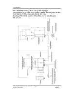
The Low Voltage Power Supply Unit mounting details are as per drawing 1954-30-026
on page 13.
Earthing
Ensure that the IS Anemometer and Power Supply Unit are Earthed via the Earth terminal
provided on the equipments in accordance with the Local or National regulations.


