Gill Instruments Ltd
Intrinsically Safe WindObserver Anemometer
Page 23
Issue 10
Doc. No. 1360-PS-0001
May 2015
5.2.7 Sealing
The connector area at the base of the anemometer
should not
be directly exposed to
moisture or solvents, as whilst the connectors are sealed when mated, the anemometer is
vented to air at the base
to avoid pressure build up. Therefore
use the gasket
provided
in the mounting kit.
5.2.8 Corrosion
Careful note should be taken of the possibility of galvanic corrosion by incorrect
mounting. It is vital that only stainless steel fixings are used and that the instrument is
insulated from the mounting surface with the rubber gasket. This will ensure that the
anemometer will provide long service under extreme conditions.
5.2.9 Earthing
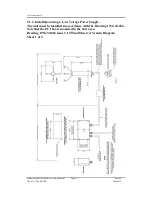
The system must be earthed in accordance with local or national regulations. Intrinsically
safe operation will be affected if incorrectly earthed. An Earth terminal is located at the
base of the IS Anemometer and to ensure correct operation, and for maximum protection
against lightning, the anemometer
MUST
be correctly earthed (grounded) via its
mountings. Inadequate Earthing will degrade anemometer performance, particularly in
the presence of radio frequency interference.
5.2.10 General
DO NOT attempt to remove or unscrew any fixing. Any unauthorised adjustment of the
unit could affect intrinsic safety and will void the warranty.
6.
SYSTEM OPERATION
6.1
Anemometer Default Settings
The factory default settings are:-
B3 F1 G0000 K1 L1 M2 NA O1 P1 U1 V1 X1
(Refer to Para 9.2 for a full explanation of the available settings).
B3:
9600 baud.
F1:
8 bits, no parity, 1 stop bit.
G0000
No averaging.
K1
IIMWV NMEA prefix.
L1
CR, LF.
M2
Polar ASCII continuous data.
NA
Node address A.
O1
Commas Separated Variable Output.
P1
1 output per second.
U1
Metres/Second.
V1
Vertical padding disabled.
X1
Align U axis with the transducer axis.


