Gill Instruments Ltd
Intrinsically Safe WindObserver Anemometer
Page 47
Issue 10
Doc. No. 1360-PS-0001
May 2015
Q- Returning to Measurement Mode (see page 42)
Road Weather Averaging Settings
RWASHORT XX (Short term number)
Where XX = 10 to 60, associated with Mode 14 and Mode 15 averaging.
RWALONG XX (Long term number)
Where XX = 1 to 10, associated with Mode 14 and Mode 15 averaging.
Ux – Digital Output Units
Units
metres/sec
(m/s)
knots
(knots)
miles / hour
(MPH)
kilometre/hour
(kph)
feet / minute
(fpm)
Configuration
code
U1
U2
U3
U4
U5
Vx- Vertical Output Padding
Setting
Configuration code
Disable vertical output padding
V1
Enable vertical output padding
V2
Xx - 45
Alignment Offset/Inverted Operation
Setting
Configuration
code
Notes
Align U axis with
transducer axis
X1
X1. Aligns U axis with North/South axis.
Align U axis +45
to transducer axis
X2
X2. This re-aligns both U&V and polarity 45˚ to
transducer axis.
Reverses Polar
Direction
X3
X3 reverses reported polar direction to allow the
instrument to be mounted upside down. N.B.
Does NOT affect UV alignment (Mode 1, 3).
Align @ 45° from
North
X4
X4 set polar alignment at 45 degrees from North
when instrument is mounted upside down.
Does NOT affect UV alignment (Mode 1, 3).
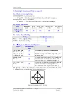
The figure below shows the polarity of U and V if the wind components along the U and
V axis are blowing in the direction of the respective arrows.
-U
+U
+V
-V
E
N
S
W
Figure of Anemometer UV Polarity


