Gill Instruments Ltd
Intrinsically Safe WindObserver Anemometer
Page 57
Issue 10
Doc. No. 1360-PS-0001
May 2015
With the Sensor connected and outputting data to the PCI box.
1.
Check that the unit is correctly configured by going into Configuration mode and
using
D3
, see Page 37.
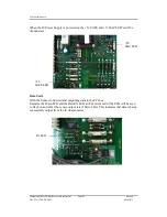
If a HyperTerminal connection is established to change the sensor configuration
then when a PC keystroke is undertaken then the PCI box Red Tx LED on the
PCB will be seen to momentarily flash on and off. This indicates a good
connection between the PC and the PCI box.
2.
Check for normal output data, and that the Status Code is OK – 00 (or A for
NMEA format).
3.
If the status code is other than these, refer to Page 41 Status (error) codes.
4.
Use an office fan or similar to check that the unit is sensing wind, turning the unit
to simulate changing wind direction and to check that both axes are functioning.
5.
Note that this is a quick functional test. There are no calibration adjustments; the
unit is designed NOT to require re-calibration within its lifetime.
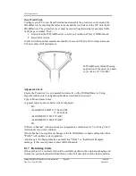
Use of the Protective Head Cover for an Integrity Check
An Integrity Check is designed to:
3.
Identify any gross changes in the head geometry that would affect the
performance.
4.
Confirm the IS WindObserver zero calibration.
The Integrity Check must be used in an indoor still air environment with an ambient
temperature between 17°C and 23°C. When conducting the test it is important that the
protective cover is assembled on to the IS WindObserver head and not touched or moved
during the test.
Tx LED


