background image


Operation 


MetPak Base Station User Manual 

Last Change 

©

 Gill Instruments Ltd


22 April, 2013 


Page 39


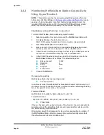
3.4.2


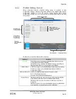
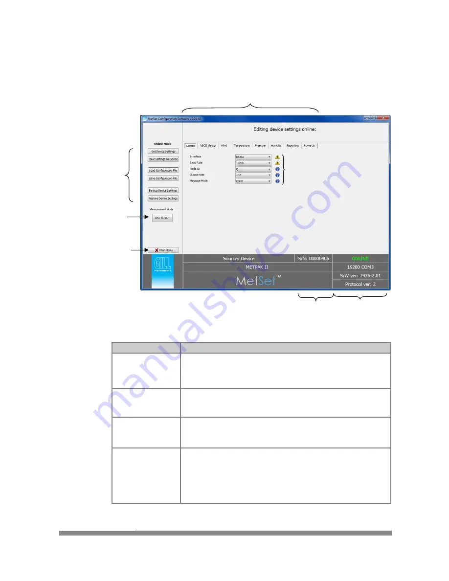
MetSet Editing Screen 

When  connected  correctly  a  MetSet  editing  screen  is  available  to  read 
configuration  settings,  change  configuration  settings,  save  MetPak  Base  Station 
configuration  settings  to  a  PC  file  location,  upload  MetPak  Base  Station 
configuration  settings  from  a  PC file  and view  the  MetPak  Base  Station  raw  data 
string output. 


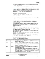
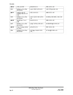
MetSet Connection Status Information. 

Reading 

Function 

ONLINE


ONLINE in green indicates the MetPak Base Station has been 
successfully connected to MetSet. 
OFFLINE in Grey indicates that MetSet is being used without a 
MetPak Base Station in communication with MetSet. 

19200 COM 3 

19200 is a report on the MetPak Base Station Baud rate setting. 

COM 3 is a report on the MetPak Base Station COM Port 
connection number. 

S/W ver 2436-2.01 

2436 is the MetPak Base Station Firmware number 

2.01 is the firmware revision. 

Protocol Ver:2 (Gill Internal Reference). 

Source:Device 

MetSet reads ‘Device’ when the source of the data that MetSet 
has retrieved has come from the MetPak Base Station. 

MetSet reads ‘File’ when the source of data has come from a 
saved file. 

MetSet reports on the connected MetPak device (e.g. METPAK) 
and reads the unit Serial Number (S/N: 00000406) 

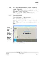
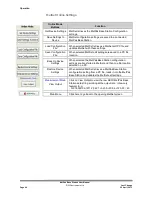
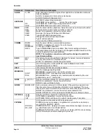
Connection Status  

MetPak Editing Pages 

MetPak Device 
Setting Options  

View MetPak 
Pro Raw Data 
Output String 

Serial Number 

Move mouse over 
exclamation or question 
marks to read setting 
comment 

Return to 
opening MetSet 
Screen 

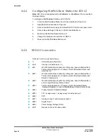
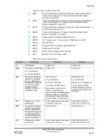
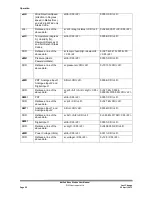
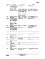
Summary of Contents for 1723-1A Series

Page 1: ...User Manual MetPak Base Station Doc No 1723 PS 0016 Issue 1 MetPak Base Station Part 1723 1A X XXX...

Page 2: ...are registered trademarks of Microsoft Corporation All other brands and product names are trademarks or registered trademarks of their respective owners Cautions and Notes The following symbols are us...

Page 3: ...tions 14 2 2 5 MetPak Base Station System Connections 18 2 2 6 Mounting MetPak Base Station 19 2 2 7 Mounting MetPak Base Station Heater Power Interface Box Optional Item 21 3 Operation 23 3 1 Start G...

Page 4: ...ions for MetPak Base Station 20 Figure 11 Opening MetView Screen 25 Figure 12 Scanning for MetPak Base Station Devices 26 Figure 13 The MetView Console 27 Figure 14 MetView Gauge Range 30 Figure 15 Me...

Page 5: ...WindObserver 70 enhanced heated or a 3 axis WindMaster or WindMaster Pro The MetPak Base Station combines all the instrument data into a single combined data string This may be configured for digital...

Page 6: ...th transducer to the South transducer and compares it with the time for a pulse to travel from S to N transducer Likewise times are compared between West and East and E and W transducer If for example...

Page 7: ...Output The Rotronic HygroClip module is a complete instrument with integrated temperature compensation Calibration data is maintained within the integrated electronics It provides digital output signa...

Page 8: ...ertz IMM International Maritime Mobile In Hg Inches of Mercury K Kelvin KPH Kilometres per Hour KTS Knots LF Line Feed M Bar Milli Bars Max Maximum MF Medium Frequency Min Minimum Mm Hg Millimetres of...

Page 9: ...y Gill see Para 2 2 3 If cables are cut and re connected incorrectly perhaps in a junction box then EMC performance may be compromised if cable screen integrity is not maintained Avoid earth loops wir...

Page 10: ...ll part 1723 10 051 or connect directly to an RS232 COM port Power Supply 12Vdc to 30Vdc at 100mA if required Belden 9503 3 pair communications and power cable if not using Gill Part 1723 10 051 lengt...

Page 11: ...a required length strip and prepare as follows 1 Trim back the screened cable outer PVC sheath to 52mm 2 Trim back the braid and drain wire to 20mm from the outer sheath 3 Separate braid and drain wir...

Page 12: ...ct into the incorrect hole it can be removed at this point by simply pulling it out Please note there will be some resistance WindSonic Option 2 RS422 10 Metre Cable Connections Connections for the Wi...

Page 13: ...be pushed back into place if the contacts are fully engaged Fit the connector to the WindSonic Sensor so that you can finish assembling the connector Screw the back shell onto the connector until it...

Page 14: ...nic except for being a 31 way type Follow the WindSonic connector assembly procedure except for WindMaster 31 way Connector Pin outs Green White wire to Connector Pin 4 Orange White wire to Connector...

Page 15: ...wer Interface Box WindObserver 70 Enhanced Heated 10 Metre Cable 8 Way Terminal Block 19 Way Connector White Green 8 or Screen Terminal Tag Cable Screen Drain wires Green White 7 M Orange White 6 R Wh...

Page 16: ...type 24AWG Wire size 7x32 AWG Cable outer diameter 6 8mm to match the hub box gland For RS422 485 operation the cable should contain twisted pairs screened to match the application The following table...

Page 17: ...t the system You can also earth the MetPak Base Station through its mountings or by connecting a grounding cable minimum of 6mm copper wire to a spare MetPak Base Station metalwork bolt hole Clean off...

Page 18: ...ough one of the gland nuts please refer to the 2nd NOTE on Page 8 5 Connect your cable as shown in the following diagrams Gill USB Cable Figure 4 RS232 Figure 5 RS422 Figure 6 RS485 Figure 7 SDI 12 Fi...

Page 19: ...PC the driver is not found by the PC then the appropriate driver to match the PC Windows version may be downloaded from http www ftdichip com Drivers VCP htm NOTE Ensure that MetPak Base Station 10 Me...

Page 20: ...necting the DC power supply as sensor power is connected to the 10 Metre cable Figure 6 RS422 connections Digital Output RS485S 2 Wire Point to Point Connections COMMS set for RS485P2W This is not the...

Page 21: ...er device Note SD 12 communications is not applicable with a 3 axis sensor connected to the Base station NOTE Ensure that MetPak Base Station 10 Metre cable is terminated before connecting the DC powe...

Page 22: ...cal Non Heated MetPak Base Station system might look like the following illustration A typical Heated MetPak Base Station system might look like the following illustration Figure 9 MetPak Base Station...

Page 23: ...ak Base Station consider the position orientation and alignment of the unit Note that the mounting pipe should first be degreased and when assembling the MetPak Base Station clamp assembly the outer c...

Page 24: ...or should be aligned to point to North or any other reference direction for example the bow of a boat Note It is usually simpler to work first with a compass at ground level and identify a suitable la...

Page 25: ...April 2013 Page 21 2 2 7 Mounting MetPak Base Station Heater Power Interface Box Optional Item This Interface box is an optional extra for orders for MetPak Base Station 1723 1A 3 211 with Heated Win...

Page 26: ......

Page 27: ...MetSet SDI 12 connection note SDI 12 is not compatible with MetSet Software NOTE MetPak Base Station is pre configured for RS232 communication factory setting If you want to use an alternative commun...

Page 28: ...MetPak Base Station will be positioned 12 Position the MetPak Base Station against the mounting post see page 22 replace the mounting bracket and tighten sufficiently to hold the unit in place but al...

Page 29: ...ck on the MetView button on your PC s desktop or choose Start Programs MetView MetView The MetView Control Centre window is displayed Scan Button If MetPak Base Station transmit and receive wires are...

Page 30: ...ate between MetView and a connected MetPak Base Station 1 Click on the Scan button to search the available COM ports for MetPak Base Station devices Figure 12 Scanning for MetPak Base Station Devices...

Page 31: ...Wind Direction Wind Speed Pressure Humidity Temperature Figure 13 The MetView Console Connection Status Table 4 Connection status indicators Reading Function Green Background Tick Indicates MetPak Ba...

Page 32: ...to read in Polar and W or U V and W output When MetView reads the 3 axis Wind data it will either be displayed in Polar and W or U V and W format as follows Note MetView cannot switch between Polar an...

Page 33: ...and Min values during current session in Temperature Dew Point Use buttons to choose from three temperature scales C F K Table 6 MetView averaging options Setting Function Real Time Choose this button...

Page 34: ...Base Station output For instance if the typical temperature measurement range required is from 10 degrees to 40 deg C then the temperature gauge range can be adjusted to reflect this Place the mouse p...

Page 35: ...essed and shown on a graph Note Data is only shown up to the time when the graph function is selected the graph is not updated once opened Data is collected from the time that MetView is opened and re...

Page 36: ...g File location Click on the Browse button to identify the folder where you want to store the data file Enter the name of the file Log file header if required type some notes on the data that is to be...

Page 37: ...d return to the console Note To show that data is being recorded the Logging button s icon changes to a green tick Logging active Logging stopped To stop logging To turn off logging 1 Click on the Log...

Page 38: ...editor or spreadsheet application Figure 19 A typical 2 Axis data log viewed in Windows Notepad Each entry in the default reporting order consists of the following 2 axis data illustrated 000001 Thu...

Page 39: ...ta Bits 8 Parity None Stop Bits 1 Flow Control None Node ID Q Output rate 1Hz Message Mode Continuous ASCII Set Up Carriage return and line feed Echo on North Alignment 0 Sensor WindSpeed On Wind Spee...

Page 40: ...rom the Exclusive OR of the bytes between and not including the STX and ETX characters Example MetPak Base Station Data String With 2 Axis wind sensor Q 249 000 01 1017 3 049 2 021 4 010 3 11 6 00 7C...

Page 41: ...or choose Start All Programs MetSet MetSet The MetSet Control Centre window is displayed If you have more than one MetPak Base Station connected to your PC MetSet by default selects the first device d...

Page 42: ...e MetPak Base Station and returns a summary of the device settings Note that MetSet also saves a copy of this screen to the connected PC as a Session Report File that can be accessed from the followin...

Page 43: ...MetPak Base Station in communication with MetSet 19200 COM 3 19200 is a report on the MetPak Base Station Baud rate setting COM 3 is a report on the MetPak Base Station COM Port connection number S W...

Page 44: ...en selected MetSet edit settings are saved to a PC file location Back Up Device Settings When selected the MetPak Base Station configuration settings are transferred to MetSet and then to a file locat...

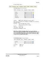
Page 45: ...57600 1200 auto selected with SDI 12 setting Node ID A to P Q to Z Output Rate 0 25Hz to 1Hz Message Mode Continuous or Polled NOTE When COMMS or Baud Rate settings are changed and Saved to Device a...

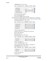
Page 46: ...Minute No Direction Wind Speed 0 00 Minimum at which Direction readings are updated The Temperature Page can be used to select Temperature Sensor ON or OFF Temperature Units C K or F Centigrade Kelvin...

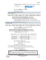
Page 47: ...ct 3 axis Parameters to Report e g NODE DIR SPEED W AXIS PRESS RH TEMP DEWPOINT VOLT STATUS NODE U AXIS V AXIS W AXIS PRESS RH TEMP DEWPOINT VOLT STATUS The PowerUp Page can be used to select Status M...

Page 48: ...t To dialog box change Connect Using to COMX where X is the number of the selected COM port Click on the OK button 6 In the COMX Properties dialog box adjust the Port settings to match the MetPak Base...

Page 49: ...er are used to enable polling or it will be missed When in polled mode when data is requested allow 570 milli seconds for the unit to respond with a line of data If the MetPak Base Station detects a p...

Page 50: ...ed received characters are only echoed while in interactive mode ECHO no parameter returns the current value EXIT Used to change the unit from SETUP mode to Measurement mode alternatively type Q or QU...

Page 51: ...only REPORT SPEED reports Polar Speed and Checksum only REPORT U AXIS or REPORT V AXIS reports U Axis Wind Speed or V Axis Wind Speed and Checksum only REPORT PRESS reports Pressure and Checksum only...

Page 52: ...tion unit 3 4 5 SDI 12 Commands SDI 12 Command Summary Unit Address default is 0 aAb Change unit address a 0 aM Wind Direction Speed direction in Degrees speed in Metres Sec Temperature degrees C Pres...

Page 53: ...ails Command Description Response Example Unit Address a CR LF 0 CR LF aAb Change the unit address a 0 the default b the new address b CR LF 1 CR LF aM Wind Direction Speed direction in Degrees speed...

Page 54: ...atttn CR LF 00051 CR LF 0D0 Retrieve a line of the above data a pressure CR LF 0 1013 0 CR LF aM5 PRT Analogue Input 1 Analogue Input 2 and Digital Input 1 Atttn CR LF 00054 CR LF 0D0 Retrieve a line...

Page 55: ...d direction in Degrees speed in Metres Sec Temperature degrees C Pressure Hecto Pascals millibars Dewpoint degrees C and CRC atttn CR LF 00056 CR LF 0D0 Retrieve a line of the above data a dir mag tem...

Page 56: ...MC7 Analogue Input 1 Analogue Input 2 and CRC Atttn CR LF 00052 CR LF 0D0 Retrieve a line of the above data a AI1 AI2 CRC CR LF 0 0000 6 0000 4FE CR LF aMC8 Digital Input 1 and CRC atttn CR LF 00051 C...

Page 57: ...Page 11 Figure 6 Method Note at this stage the MetPak Base Station supply to be switched off Open a Terminal program e g Gill WIND Software http www gill co uk main software html or Windows HyperTermi...

Page 58: ...r to exit SAFE MODE Data will now scroll on screen Note however for RS232 changes to take place the unit must be powered down and back up again Close the 4800 baud rate Wind or HyperTerminal Program P...

Page 59: ...empt to obtain communication with the MetPak Base Station Corrupted output Check that the communication settings of the MetPak Base Station and host system match Try a slower baud rate Check cable len...

Page 60: ...led V and W axis blocked or faulty WindMaster Pro only 07 Wind Sensor Axis 1 2 and 3 failed U V and W axis blocked or faulty WindMaster Pro only 08 Wind Sensor NVM error Non Volatile Memory checksum f...

Page 61: ...ows 1 Connect the MetPak Base Station unit to the host PC and power supply using a known working test cable 2 Check that the unit is correctly configured by going into Set Up mode using MetSet 3 Check...

Page 62: ......

Page 63: ...mend replacement of the temperature and humidity probe filter every 6 months to ensure proper performance Corroded discoloured or clogged dust filters should be replaced If the filter is not replaced...

Page 64: ...ub box dry If you do not replace the filter every 24 months you may start to see elevated or erroneous readings of the pressure sensor with time and this behaviour can be corrected by replacement of t...

Page 65: ...ometer Manual for full details Range 0 45m s WindMaster 0 60m s WindSonic WindSonic M 0 65m s WindMaster Pro 0 70m s WindObserver 70 Accuracy 2 12m s Resolution 0 01m s Threshold 0 01m s Wind Directio...

Page 66: ...tput 0 25 0 5 1 Hz or Polled Mode MetPak Base Station Status Status codes provided within the data message string RS485 2 wire point to point only Power Supply Input voltage RS232 RS422 RS485 12v to 3...

Page 67: ...UV Stabilised white thermoplastic Wind Sensor and Hygroclip Mountings and anodized Aluminium bracket Fittings Stainless Steel 316 bracket fittings supplied for clamping to a vertical pipe diameter of...

Page 68: ...Grey Supply ve Signal 0V 6 Green Supply ve 3 3V DC Table 14 Wind Sensor 10 Metre Cable connections 8 way connector J4 Connector J4 Wire Colour Signal Name 1 Brown White RSR422 Anemometer Output to Hub...

Page 69: ...n conformity with the protection requirements of Council Directive 2004 108 EC on the approximation of the laws relating to electromagnetic compatibility This Declaration of Conformity is based upon c...

Page 70: ...ruments Limited Saltmarsh Park 67 Gosport Street Lymington Hampshire SO41 9EG Tel 44 0 1590 613500 Fax 44 0 1590 613501 E mail anem gill co uk Website www gill co uk Copyright Gill Instruments 2011 Re...

Reviews: