background image


User Manual 

MetPak RG  

Weather Station 

Doc No. 1723-PS-0013 

Issue A


MetPak RG Part: 1723-3B-2-111 

Summary of Contents for MetPak RG

Page 1: ...User Manual MetPak RG Weather Station Doc No 1723 PS 0013 Issue A MetPak RG Part 1723 3B 2 111...

Page 2: ...or terms of guarantee please contact your supplier Warranty is void if the coloured Wind Sensor security seal is damaged or broken or the Wind Sensor transducer caps have been damaged Trademarks Micro...

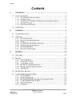
Page 3: ...ired 6 2 2 3 Cabling 6 2 2 4 Communication and Power Connections 9 2 2 5 Digital Rain Gauge Connections 13 2 2 6 Mounting MetPak RG 14 2 2 7 Mounting the Rain Gauge 16 3 Operation 19 3 1 Start Guide 1...

Page 4: ...ectrical Conformity Certificate vi Figures Figure 1 MetPak RG Parts 1 Figure 2 Compass points 2 Figure 3 Internal view of the hub box 9 Figure 4 Hub Box with Digital Pec fitted 10 Figure 5 Connection...

Page 5: ...ns 25 Table 6 MetView averaging options 25 Table 7 Max min markers 25 Table 8 MetView Screen Settings Options 25 Table 9 Default configuration settings 31 Table 10 MetPak RG Commands 41 Table 11 Commo...

Page 6: ...Contents MetPak RG User Manual Gill Instruments Ltd Last Change Page 4 12 February 2013 Intentionally Blank...

Page 7: ...ndustry standard sensor The customer is able to add one supplied digital contact closure rain gauge The MetPak RG combines all the instrument data into a single combined data string This may be config...

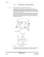
Page 8: ...ransducer Likewise times are compared between West and East and E and W transducer If for example a North wind is blowing then the time taken for the pulse to travel from N to S will be faster than fr...

Page 9: ...Barometric Pressure Barometric pressure output is provided by a solid state device fitted on to the circuit board in the MetPak RG Hub box Vent to atmosphere is via a Gortex filter which also protect...

Page 10: ...MM International Maritime Mobile In Hg Inches of Mercury K Kelvin KPH Kilometres per Hour KTS Knots LF Line Feed M Bar Milli Bars Max Maximum MF Medium Frequency Min Minimum Mm Hg Millimetres of Mercu...

Page 11: ...re that the power supply operates to the MetPak RG specification see Para 6 1 at all times Avoid turbulence caused by surrounding structures that will affect the accuracy of the sensors such as trees...

Page 12: ...S232 communication factory default setting and matching Rain Gauge 1723 10 051 MetPak RG RS232 to USB 1 8M configuration cable with integral 5v power or alternatively use RS232 RS232 converter and sep...

Page 13: ...ws an example manufacturers reference other manufacturers equivalents can be used Table 2 Recommended Belden cable types Application No of Pairs Belden Ref Rain Gauge Connection 1 8761 SDI 12 or RS485...

Page 14: ...sure correct operation and for maximum protection from lightning a separate lightning rod system is recommended to protect the system You can also earth the MetPak RG through its mountings or by conne...

Page 15: ...ble through one of the gland nuts please refer to the 2nd NOTE on Page 8 5 Connect your cable as shown in the following diagrams Gill USB Cable Figure 5 RS232 Figure 6 RS422 Figure 7 RS485 Figure 8 SD...

Page 16: ...t using the Gill Configuration Cable 1723 10 051 J5 Pin 1 2 3 4 5 6 7 8 Colour None None Yellow Orange None None Black Red Figure 5 Connection of Gill USB Cable Part No 1723 10 051 NOTE If upon connec...

Page 17: ...creen wires NA Chassis Ground V supply V supply 7 8 DC Power supply Figure 6 RS232 connections Digital Output RS422 Connections COMMS set for RS422 This is not the default communications setting ensur...

Page 18: ...e Signal Names RS485 TX RS485 RX 6 5 RS485TX RX RS485 TX RS485 RX 3 4 RS485TX RX Signal 0v 2 Signal Ground Chassis Ground Terminal Post Screen wires Chassis ground Power 0v Power ve 7 8 DC Power Suppl...

Page 19: ...en MetPak RG s hub box by unfastening the four screws 2 Locate connector J8 see Figure 3 3 Pass the cable through one of the gland nuts see Note below 4 Connect the cable as detailed in Figure 10 5 At...

Page 20: ...radar or radio transmitters A site survey may be required if there is any doubt about the strength of external electrical noise Orientation Normally the MetPak RG is mounted on a vertical pole ensurin...

Page 21: ...MetPak RG Note that the mounting pipe should first be degreased and when assembling the MetPak clamp assembly the outer clamp nuts need to be tightened evenly to a torque figure of 3 Nm The moving pl...

Page 22: ...ample It is suggested that rawlbolts are used for this purpose as they provide a means of levelling the rain gauge Unscrew the 3 upper nylon thumb nuts and remove all the nylon spacers from the studs...

Page 23: ...umb nuts ensuring that the spirit level bubble remains within the centre circle NOTES Ensure that the Foam insert under the tipping bucket is removed before re fitting the funnel No two rain gauge des...

Page 24: ...Contents MetPak RG User Manual Gill Instruments Ltd Last Change Page 18 12 February 2013 Intentionally Blank...

Page 25: ...MetPak RG is pre configured for RS232 communication factory setting If you want to use an alternative communication protocol you will need to set up the unit using an RS232 connection with an appropri...

Page 26: ...ainst the mounting post see page 15 fit the mounting kit bracket and tighten sufficiently to hold the unit in place but allowing it to be rotated or moved up and down the pole 10 Check the orientation...

Page 27: ...s desktop or choose Start Programs MetView MetView The MetView Control Centre window is displayed Scan Button If MetPak RG transmit and receive wires are connected to the PC then use the Scan button t...

Page 28: ...ces To set up communicate between MetView and a connected MetPak RG Click on the Scan button to search the available COM ports for MetPak RG devices Figure 13 Scanning for MetPak RG Devices When a dev...

Page 29: ...t show data if the unit is set for NMEA or SDI 12 format Wind Direction Wind Speed Pressure Humidity Temperature Rainfall Figure 14 The MetView Console Connection Status Table 4 Connection status indi...

Page 30: ...ments are shown in the MetView display reflects the order in which the instrument data appears in the MetPak RG data string DIG 1 Input with user definable title On switch on MetView commences an incr...

Page 31: ...oint Use buttons to choose from three temperature scales C F K DIG1 Typically for Rain buttons available for inches or millimetres and a reset button Table 6 MetView averaging options Setting Function...

Page 32: ...MetPak RG output For instance if the typical temperature measurement range required is from 10 degrees to 40 deg C then the temperature gauge range can be adjusted to reflect this Place the mouse poi...

Page 33: ...cessed and shown on a graph Note Data is only shown up to the time when the graph function is selected the graph is not updated once opened Data is collected from the time that MetView is opened and r...

Page 34: ...Click on the Browse button to identify the folder where you want to store the data file Enter the name of the file Log file header If required type some notes on the data that is to be recorded which...

Page 35: ...ing and return to the console Note To show that data is being recorded the Logging button s icon changes to a green tick Logging active Logging stopped To stop logging Click on the Logging button on t...

Page 36: ...et application Figure 19 A typical data log viewed in Windows Notepad Each entry in the default reporting order consists of the following 000001 Wed 14 November 2012 12 37 31 Q 262 000 04 1024 3 051 6...

Page 37: ...CII Set Up Carriage return and line feed Echo on North Alignment 0 Sensor WindSpeed On Wind Speed Units MS Metres Second Temperature Sensor On Temperature Units C Degrees Celsius Dewpoint Sensor On De...

Page 38: ...Temperature Dewpoint Digital Input 1 Supply voltage Status code ETX Checksum Carriage Return Line Feed NOTES STX is the Start of String character ASCII value 2 ETX is the End of String character ASCII...

Page 39: ...DIG 1 enabled In Polled Mode The MetPak RG will store and output the cumulative total number of switch closures since the last poll request Once the cumulative total has been output the count will be...

Page 40: ...ed PC as a Session Report File that can be accessed from the following destination C Program Files X86 Gill Instruments MetSet SessionReports Close this screen to go to the Editing screens Disconnect...

Page 41: ...ing used without a MetPak RG in communication with MetSet 19200 COM 6 19200 reports on the MetPak RG Baud rate setting COM 6 reports on the MetPak RG COM Port connection number S W ver 2436 B 39 2436...

Page 42: ...hen selected MetSet edit settings are saved to a PC file location Back Up Device Settings When selected the MetPak RG configuration settings are transferred to MetSet and then to a file location selec...

Page 43: ...o selected with SDI 12 setting Node ID A to P Q to Z Output Rate 0 25Hz to 1Hz Message Mode Continuous or Polled NOTE When COMMS or Baud Rate settings are changed and Saved to Device a warning is issu...

Page 44: ...r Miles Hour Kilometres Hour Feet Minute The Temperature Page can be used to select Temperature Sensor ON or OFF Temperature Units C K or F Dew Point Sensor ON or OFF Dew Point Units C K or F Centigra...

Page 45: ...G1 VOLT STATUS CHECK Units Message Output ON or OFF e g DEG MS HPA C C MM V DIG1 CONFIGURED The DIG1 Page can be used to select DIG1 Sensor ON or OFF Sensor Type Should be left selected to RAIN Units...

Page 46: ...of the selected COM port Click on the OK button 6 In the COMX Properties dialog box adjust the Port settings to match the MetPak RG unit s settings The default settings are Bits per second 19200 Data...

Page 47: ...hen in polled mode when data is requested allow 570 milli seconds for the unit to respond with a line of data If the MetPak RG detects a pressure temperature humidity sensor fault then allow 4 seconds...

Page 48: ...ry Unit Address default is 0 aAb Change unit address a 0 aM Wind Direction Speed direction in Degrees speed in Metres Sec Temperature degrees C Pressure Hecto Pascals millibars and Humidity aM1 Wind D...

Page 49: ...F aAb Change the unit address a 0 the default b the new address b CR LF 1 CR LF aM Wind Direction Speed direction in Degrees speed in Metres Sec Temperature degrees C Pressure Hecto Pascals millibars...

Page 50: ...nse Example aMC Wind Direction Speed direction in Degrees speed in Metres Sec Temperature degrees C Pressure Hecto Pascals millibars Humidity and CRC atttn CR LF a is unit identifier ttt is time in se...

Page 51: ...2 7 009 0LV CR L F aMC4 Pressure Hecto Pascals millibars and CRC atttn CR LF 00051 CR LF 0D0 Retrieve a line of the above data a pressure CRC CR LF 0 1017 8GM CR LF aMC8 Digital Input 1 and CRC atttn...

Page 52: ...ftware that the Tools features are not applicable Open Gill Wind Software Serial Port Set the drop down menu to the required COM Port Connection Click on the OK button Baudrate Set the drop down menu...

Page 53: ...ogram Power down the MetPak RG and re apply power Open a new Wind or HyperTerminal program at 19200 baud rate RS232 data will now scroll on screen at the MetPak RG default 19200 baud rate The command...

Page 54: ...ettings of the MetPak RG and host system match Try a slower baud rate Check cable lengths and type of cable One way communication Check that the wiring is in accordance with the manual Unexpected Temp...

Page 55: ...re than one fault Fault condition that can be the sum of 0B 10 20 or 40 e g 1B would mean that both the Wind Sensor 0B and Hygroclip 10 were faulty 4 2 Servicing In the event of failure prior to retur...

Page 56: ...led slowly pour in water to see make and break connections and momentary readings of 47 ohms in each tip direction 3 If the unit is disassembled gently move the tipping bucket arm to the upright posit...

Page 57: ...ill highly recommend replacement of the temperature and humidity probe filter every 6 months to ensure proper performance Corroded discoloured or clogged dust filters should be replaced If the filter...

Page 58: ...lace the filter unscrew the 4 screws retaining the hub box lid Remove the existing Gore Tex filter and M12 Nut Fit and secure the new filter with the nut provided Re fit the 4 lid screws Should you be...

Page 59: ...t 1723 PK 114 8 Remove and clean any dirt from the tipping buckets being careful not to tip the bucket should the rain gauge still be logging 9 Check that the gauge is still level It is possible for t...

Page 60: ...f a replacement or re calibrated Rain Gauge is used then the Hub box will need programming using MetSet with the new tip calibration factor if this has changed Calibration figures can be seen on the l...

Page 61: ...urement m s knots mph kph ft min Wind Speed Range 0 60m s 0 134mph Accuracy 2 12m s Resolution 0 01m s 0 02mph Threshold 0 01m s 0 02mph Wind Direction Range 0 359 Degrees No dead band Accuracy 3 12m...

Page 62: ...act Closure input tipping bucket rain gauge capable of capturing events up to 10Hz Digital Input Capable of detecting an event with a duration of greater than 1 4mS Digital Input Capable of detecting...

Page 63: ...ss Steel 316 bracket fittings supplied for clamping to a vertical pipe of diameter 30mm to 58mm Overall Dimensions 350mm x 287mm x 142mm excluding bracket clamp Weight 2 1kg including bracket Software...

Page 64: ...RG Hub box Factory Connections Table 13 HygroClip connections 6 way connector J1 Connector J1 Wire Colour Signal Name 1 No Connection 2 Blue RXD from HygroClip UART 3 Red TXD to HygroClip UART 4 Yell...

Page 65: ...r J5 Connector J5 Signal Name 1 SDI 12 TX RX 2 Signal 0V 3 RS232 TX or RS422 RS485 TX HUB to user 4 RS232 RX or RS422 RX User to HUB 5 RS422 RX User to HUB 6 RS422 RS485 TX HUB to User 7 Supply 0v 8 S...

Page 66: ...otection requirements of Council Directive 2004 108 EC on the approximation of the laws relating to electromagnetic compatibility This Declaration of Conformity is based upon compliance of the product...

Page 67: ...struments Limited Saltmarsh Park 67 Gosport Street Lymington Hampshire SO41 9EG Tel 44 0 1590 613500 Fax 44 0 1590 613501 E mail anem gill co uk Website www gill co uk Copyright Gill Instruments 2011...

Reviews: