HS-50 & HS-100
Doc. No 1199-PS-0035 Issue 3
June 2021
___________________________________________________________________________________________
Page 9
7.4 Polar definition
The wind speed in the UV plane, with direction in degrees from 0 to 359
, with respect to the
Reference spar (which is normally aligned to North).
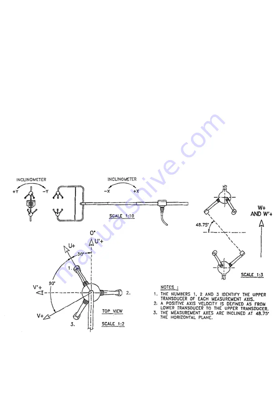
7.5 U, V, and W Axes definition (See fig 2).
+U is defined as towards the direction in line with the north spar as indicated in the diagram.
+V is defined as towards the direction of 90
anti-clockwise from N / the Reference spar.
+W is defined as vertically up the mounting shaft.
Note, when the unit is configured for the
ALIGN AXIS
setting the UV definition rotates 30 degrees
anti-clockwise such that U is now in line with transducer axis 1.
7.6 Alignment, Dimensions & Orientation
It is recommended that the head is aligned so that the upper transducer sphere is directly above the
lower transducer sphere. The inclinometer has been calibrated to read zero on both axes when this
position is reached.
Figure 2 shows the direction and polarity for the UVW axes
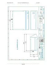
Figure 3 shows the dimension & alignment information for the system.
Figure 2 U, V and W Axes Definition
Summary of Contents for 1199-PK-085
Page 1: ......


