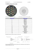
HS-50 & HS-100
Doc. No 1199-PS-0035 Issue 3
June 2021
___________________________________________________________________________________________
Page 10
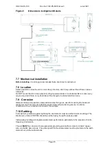
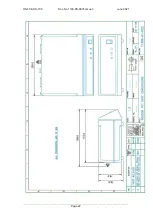
Figure 3
Dimensions & Alignment Details
7.7 Mechanical installation
Before installing
, it is strongly recommended that a bench test is carried out.
7.8 Location
Select a position so that the unit is clear of any structure, which may obstruct the airflow or induce
turbulence.
Do NOT mount the HS in close proximity of high-powered radar or radio transmitters. A site survey
may be required if there is any doubt about the strength of external electrical noise.
7.9 Corrosion
Galvanic corrosion is possible unless stainless steel fixings are used for mounting the head and
electronics unit. This will ensure that the anemometer will provide long service in extreme
conditions such as a marine environment, for example.
7.10 Earthing
For maximum protection against lightning the anemometer must be earthed via its mountings. The
Electronics unit and PCI/PCIA should be earthed using the earth studs provided.
Inadequate grounding will degrade anemometer performance, particularly in the presence of radio
frequency interference.
The unit
MUST
be connected to an appropriate grounding point with a minimum of 6mm² copper
wire, via the M4 base screws. The primary earth for the anemometer must be provided via the earth
stud and not via the cable screens.
Summary of Contents for 1199-PK-085
Page 1: ......


