Engine
0
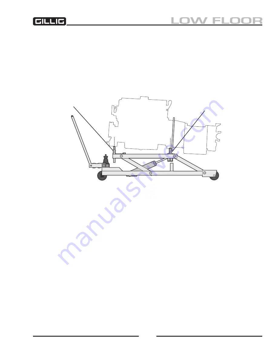
8. Adjust the height of the rear adjustment screws as required and raise the upper platform until the
engine/transmission assembly is fully supported by the dolly.
9. Remove the bell housing bushing bolts and chassis mounted support brackets.
10. Remove the transmission tail support bushing bolt, if installed.
11. Remove the rear support angle from the chassis rails.
12. Remove the engine/transmission assembly by rolling the dolly toward the rear of the bus.
Figure 3-17, Mating Dolly To Engine
20-100-188
rear Adjustment screws
bell housing cradle
Summary of Contents for LOW FLOOR
Page 18: ...Specifications 18...
Page 58: ...Preventive Maintenance 58...
Page 110: ...Engine 110...
Page 138: ...Transmission Driveline Rear Axle 138...
Page 182: ...Suspension 182...
Page 260: ...Air System 260...
Page 420: ...Electrical System 420 Deutsch DT Series Connectors...
Page 421: ...Electrical System 421...
Page 422: ...Electrical System 422 Deutsch HD 10 Series Connectors...
Page 423: ...Electrical System 423...
Page 424: ...Electrical System 424 Deutsch HD 30 Series Connectors...
Page 425: ...Electrical System 425...
Page 442: ...Heating Air Conditioning 442...
Page 492: ...Body and Interior 492 Figure 11 33 USSC Seat Assembly...
Page 493: ...Body and Interior 493 Figure 11 34 USSC Seat Suspension Assembly...
Page 495: ...Body and Interior 495 Figure 11 37 Seat Air Connections...


