22
Transmission/Driveline/Rear Axle
why gauge readings are superior to dipstick readings
The Davco FT2200 Transmission Fluid Level Gauge is temperature compensated from 125°F to 220°F.
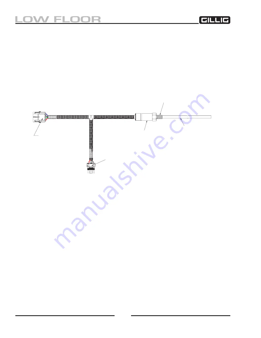
The sensor probes and electronic housing that communicate with this gauge can replace the dipstick in
the dipstick/fill tube (see Figure 4-4
). Manual dipsticks provide this same function by having hot marks
and cold marks, but since transmission fluid expansion is spread across the entire possible temperature
range, manual dipsticks will only be correct at two distinct temperatures (cold marks are set for approxi-
mately 70°F, while hot marks are for approximately 180°F). Because of this, manual dipsticks will only
give correct level readings when fluid temperature is close to either of these points. The FT2200 is de
-
signed to give temperature compensated readings which are correct for the entire working range between
125°F to 220°F. Because of this, the gauge is generally more accurate and easier to read than a dipstick.
For more information on the Davco FT2200 transmission fluid level gauge, please contact your Gillig
Service representative, or contact Davco Technology:
Davco Technology
1600 Woodland Drive
Saline MI 47176
(800) 328-2611
www.davcotec.com
Level Sensor Probe
Electronics
Connector # 2020830
A - Power (RED)
B - Level Signal Output (GREEN)
C - Ground (BLACK)
D - Temperature Sensor Output
M4-.5
Connector # 205793
A - Power (RED)
B - Signal (WHITE)
C - Ground (BLACK)
Figure 4-4, “Electronic Dipstick”
Summary of Contents for LOW FLOOR
Page 18: ...Specifications 18...
Page 58: ...Preventive Maintenance 58...
Page 110: ...Engine 110...
Page 138: ...Transmission Driveline Rear Axle 138...
Page 182: ...Suspension 182...
Page 260: ...Air System 260...
Page 420: ...Electrical System 420 Deutsch DT Series Connectors...
Page 421: ...Electrical System 421...
Page 422: ...Electrical System 422 Deutsch HD 10 Series Connectors...
Page 423: ...Electrical System 423...
Page 424: ...Electrical System 424 Deutsch HD 30 Series Connectors...
Page 425: ...Electrical System 425...
Page 442: ...Heating Air Conditioning 442...
Page 492: ...Body and Interior 492 Figure 11 33 USSC Seat Assembly...
Page 493: ...Body and Interior 493 Figure 11 34 USSC Seat Suspension Assembly...
Page 495: ...Body and Interior 495 Figure 11 37 Seat Air Connections...


