50
Suspension
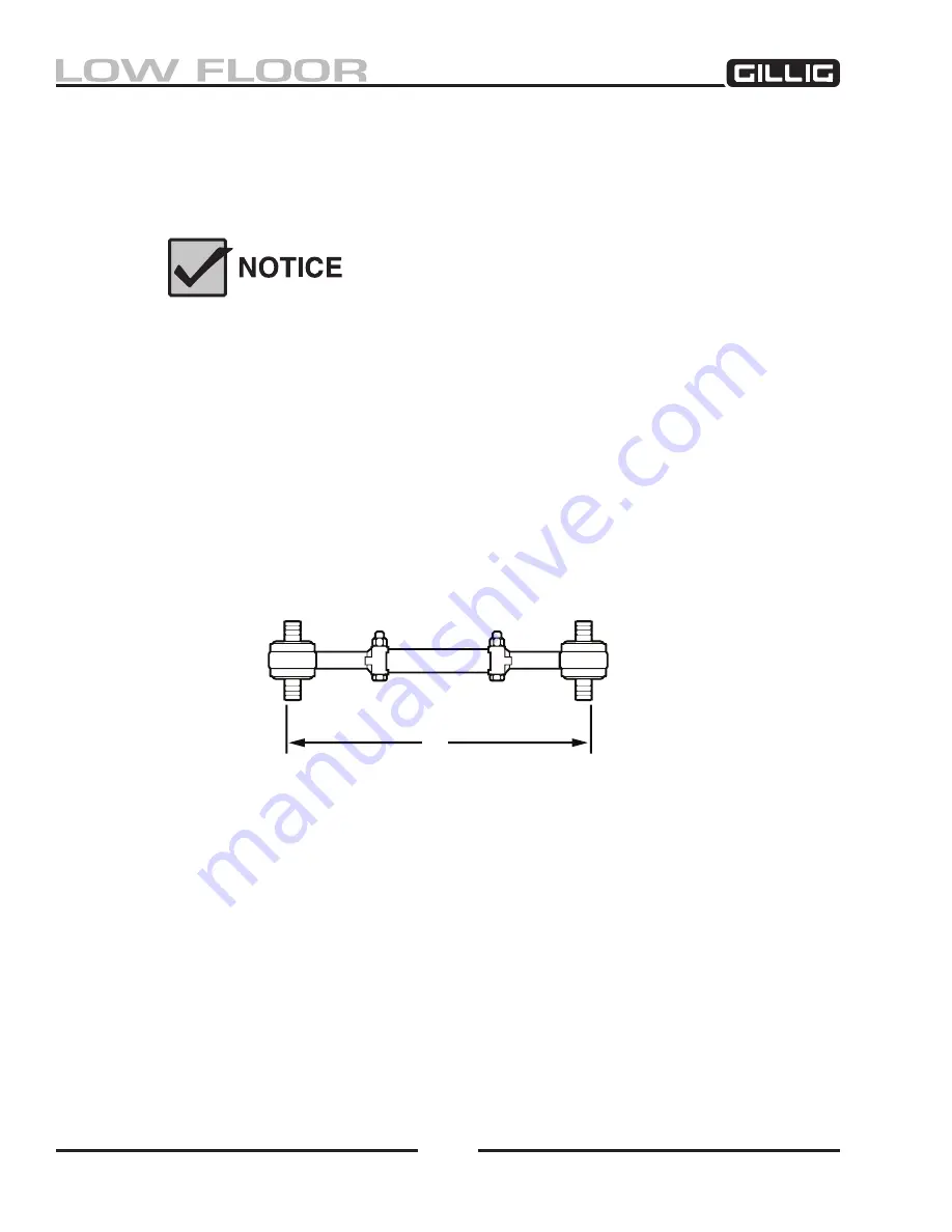
Figure 5-4, Nominal Torque Rod Length
A
4. Thoroughly inspect the torque rod for any signs of shearing, bushing deterioration, or other dam
-
age including cracking or bending.
5. Replace any damaged parts with new parts. The length of the torque rods should be measured
as shown in Figure 5-
4; nominal dimension “A” should be 20.20" for upper rods and 22.88" for
lower rods. Be sure clamp bolts are properly tightened.
The torque rod dimensions stated in Step 4 should be considered
nominal. In some cases it may be necessary to measure the old torque
rod and adjust the new one to the same length. Always perform a full
suspension inspection and alignment after changing or adjusting torque
rods, including a check of caster, wheelbase, and air bag straightness.
6. Inspect the axle bracket boss for any excessive wear.
7. Install the torque rod into the mounting brackets in the suspension tower and the air spring
mounting assembly. Spray a suitable anti-rust lubrication on the threads before assembly. Make
sure the right hand threaded end is attached to the air spring mounting assembly. Do not attach
the rod end with the right hand threads to the suspension tower.
8. Install the bolts, washers, and nuts into the ends of the rod. Tighten the nuts to the specified
torque.
Summary of Contents for LOW FLOOR
Page 18: ...Specifications 18...
Page 58: ...Preventive Maintenance 58...
Page 110: ...Engine 110...
Page 138: ...Transmission Driveline Rear Axle 138...
Page 182: ...Suspension 182...
Page 260: ...Air System 260...
Page 420: ...Electrical System 420 Deutsch DT Series Connectors...
Page 421: ...Electrical System 421...
Page 422: ...Electrical System 422 Deutsch HD 10 Series Connectors...
Page 423: ...Electrical System 423...
Page 424: ...Electrical System 424 Deutsch HD 30 Series Connectors...
Page 425: ...Electrical System 425...
Page 442: ...Heating Air Conditioning 442...
Page 492: ...Body and Interior 492 Figure 11 33 USSC Seat Assembly...
Page 493: ...Body and Interior 493 Figure 11 34 USSC Seat Suspension Assembly...
Page 495: ...Body and Interior 495 Figure 11 37 Seat Air Connections...


