7
Suspension
Turning Angle Adjustment
The stop bolt should not touch the axle beam when the steering gear is
providing power assist. The poppet valves in the steering gear should
be bypassing pressure before the stop bolt comes into contact with the
axle beam.
NEVER increase the vehicle’s maximum turn angle beyond 45
degrees.
The turning angle is the maximum angle through which the wheels may be turned from the straight
ahead position. This turning angle is greater for the inside wheel than for the outside wheel in a turn.
Before adjusting the turning angle, be sure the front end is properly aligned. Poppet valves at both ends
of the power steering gear, after being properly adjusted, automatically unload the hydraulic system to
protect the mechanism from undue strain and damage. Refer to the TRW documentation included with
your bus for steering gear adjustment procedures.
The maximum turning angle, which is measured at
the inner wheel during a turn, is 45 degrees.
Use an accurate turning angle instrument to make correct
angular measurements.
1. Turn the steering wheel to the left until the turning angle (as measured at the left wheel) reaches
45 degrees
.
2. Loosen the jam nut and turn the stop bolt to just
contact the axle beam.
3. Tighten the jam nut to 65–85 lb-ft
(68–101 N-m).
4. Repeat steps 1 through 3 for the right steering
knuckle, this time turning the wheel to the right
and measuring the turning angle at the right
wheel.
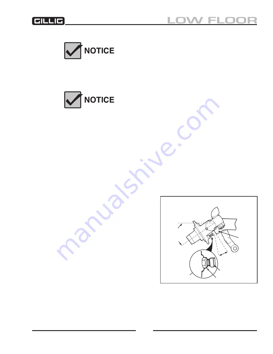
5. Check to be sure that the poppet valves in the
steering gear automatically bypass hydraulic
pressure
before
the stop bolts contact the axle
beam (an easily audible sound will be heard
from the steering gear when pressure bypass
occurs). There should be approximately 0.125"
between the stop bolt and the axle beam when
the poppet valves relieve hydraulic pressure (see
Figure 5-11).
Figure 5-11, Knuckle Stop Bolt Clearance
Two-Piece Steering Stop Bolt
STOP BOLT
JAM NUT
AxLE
BEAM
STOP
SCREW
BOSS
2-PIECE
STOP BOLT
ASSEMBLy
MAxIMUM
TURN
ANGLE
0.25" (3mm)
Summary of Contents for LOW FLOOR
Page 18: ...Specifications 18...
Page 58: ...Preventive Maintenance 58...
Page 110: ...Engine 110...
Page 138: ...Transmission Driveline Rear Axle 138...
Page 182: ...Suspension 182...
Page 260: ...Air System 260...
Page 420: ...Electrical System 420 Deutsch DT Series Connectors...
Page 421: ...Electrical System 421...
Page 422: ...Electrical System 422 Deutsch HD 10 Series Connectors...
Page 423: ...Electrical System 423...
Page 424: ...Electrical System 424 Deutsch HD 30 Series Connectors...
Page 425: ...Electrical System 425...
Page 442: ...Heating Air Conditioning 442...
Page 492: ...Body and Interior 492 Figure 11 33 USSC Seat Assembly...
Page 493: ...Body and Interior 493 Figure 11 34 USSC Seat Suspension Assembly...
Page 495: ...Body and Interior 495 Figure 11 37 Seat Air Connections...


