94
Air System
Operation
The compressor is driven by the engine and its crankshaft turns continuously while the engine is run-
ning. Compression of air is controlled by the governor and by the compressor’s unloading mechanism.
The governor maintains the brake system air pressure at preset maximum and minimum levels.
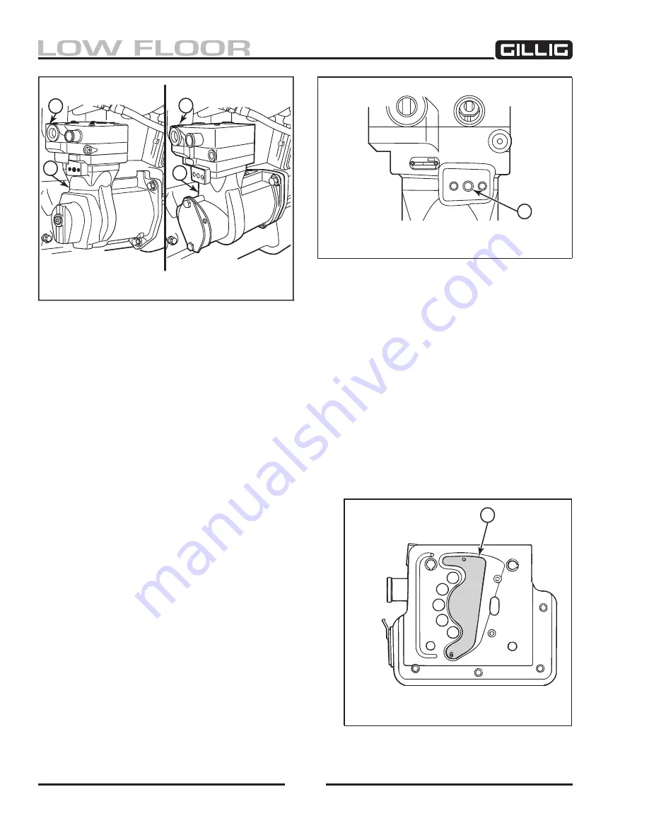
The governor is mounted apart from the compressor, either horizontally or vertically. The governor port
is located on the crankcase of the compressor (Figure 6-7).
The unloader mechanism controls the air compression cycle; an air compression cycle has three phases:
1. Induction: Air flows from the engine to the compressor, opening an inlet valve in the cylinder
head of the compressor.
2. Compression: Air pressure is increased, caus-
ing the compressor’s discharge valve to open.
3. Unloading: Air passes from the cylinder to
the inlet chamber of the cylinder head via a
port controlled by a sliding leaf valve. When
system cut-in pressure (110 psi) is reached, air
is exhausted from the unloader port.
After unloading, the unloader piston returns
the sliding leaf valve to the loaded position.
This seals the unloader ports and compression
resumes (Figure 6-8).
CyLINDER HEAD
2
CRANKCASE (CyLINDER BLOCK)
NON-THROUGH DRIVE
THROUGH DRIVE
2
2
Figure 6-6, Compressor Subassemblies
GOVERNOR PORT
Figure 6-7, Governor Port
SLIDING LEAF VALVE
Figure 6-8, Sliding Leaf Valve
Summary of Contents for LOW FLOOR
Page 18: ...Specifications 18...
Page 58: ...Preventive Maintenance 58...
Page 110: ...Engine 110...
Page 138: ...Transmission Driveline Rear Axle 138...
Page 182: ...Suspension 182...
Page 260: ...Air System 260...
Page 420: ...Electrical System 420 Deutsch DT Series Connectors...
Page 421: ...Electrical System 421...
Page 422: ...Electrical System 422 Deutsch HD 10 Series Connectors...
Page 423: ...Electrical System 423...
Page 424: ...Electrical System 424 Deutsch HD 30 Series Connectors...
Page 425: ...Electrical System 425...
Page 442: ...Heating Air Conditioning 442...
Page 492: ...Body and Interior 492 Figure 11 33 USSC Seat Assembly...
Page 493: ...Body and Interior 493 Figure 11 34 USSC Seat Suspension Assembly...
Page 495: ...Body and Interior 495 Figure 11 37 Seat Air Connections...


