Hydraulic System
305
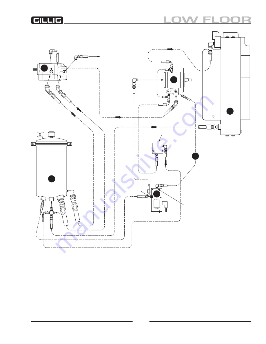
Figure 8-2, Hydraulic System Schematic
2
Power Steering
Return
Return
(marked with “t”
for tank return)
Fan Control
Valve
Fan Motor
Hydraulic
Reservoir
Cooler
Pump
A
C
E
D
B
F
Bypass Relief
Valve 00 PSI
Cracking Pressure
Pressure Port
(marked with “p”)
Inlet ports from
Top View—
reservoir are at
bottom of pump.
To Power
Steering
Summary of Contents for LOW FLOOR
Page 18: ...Specifications 18...
Page 58: ...Preventive Maintenance 58...
Page 110: ...Engine 110...
Page 138: ...Transmission Driveline Rear Axle 138...
Page 182: ...Suspension 182...
Page 260: ...Air System 260...
Page 420: ...Electrical System 420 Deutsch DT Series Connectors...
Page 421: ...Electrical System 421...
Page 422: ...Electrical System 422 Deutsch HD 10 Series Connectors...
Page 423: ...Electrical System 423...
Page 424: ...Electrical System 424 Deutsch HD 30 Series Connectors...
Page 425: ...Electrical System 425...
Page 442: ...Heating Air Conditioning 442...
Page 492: ...Body and Interior 492 Figure 11 33 USSC Seat Assembly...
Page 493: ...Body and Interior 493 Figure 11 34 USSC Seat Suspension Assembly...
Page 495: ...Body and Interior 495 Figure 11 37 Seat Air Connections...


