Hydraulic System
32
Fan Motor Removal
1. Disconnect the battery ground cable
to ensure that the coach cannot be
started while work on the hydraulic
system is underway.
2. Prepare a catch basin for hydraulic
fluid drainage. Discard any fluid
which is removed from the system.
DO NOT reuse fluid
.
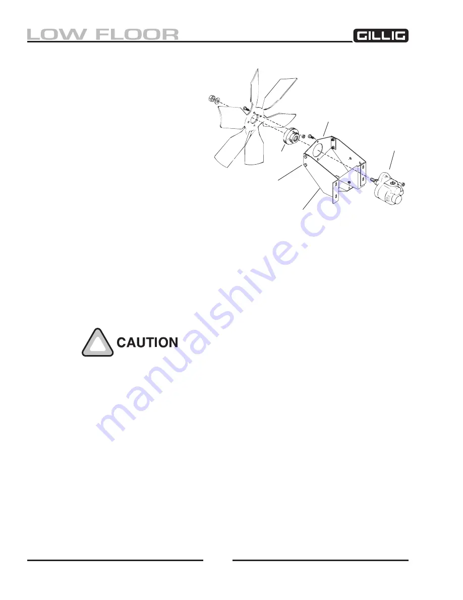
3. See Figure 8-
5. Disconnect the hose
at the bottom of the motor and al-
low the motor to drain. Turn the fan
blade approximately ten turns to help
purge any fluid trapped in the gear
teeth.
4. Disconnect the hoses from the con
-
trol valve which is mounted directly
on the motor. Plug or cap all fluid
system openings to preclude entry of foreign matter into the hydraulic system.
5. Disconnect the Weather-pak™ electrical connection from the valve. Mark the wires to ensure
that they are properly connected later when the motor is installed.
6. Remove the four bolts attaching the fan blade to the hub on the motor output shaft. Lay the fan
blade flat against the radiator inside the shroud.
Take care to avoid damage to the inside of the radiator core when the
fan is leaned against it.
7. Remove the two fan motor retaining bolts, washers, and locknuts. Slide the motor toward the
engine and remove it from the coach. It is easier to remove the motor from below.
BRACKET
MOTOR
CHANNEL
FAN HUB
ISOLATORS
06-002-00
Figure 8-5, Hydraulic Motor/Valve
Summary of Contents for LOW FLOOR
Page 18: ...Specifications 18...
Page 58: ...Preventive Maintenance 58...
Page 110: ...Engine 110...
Page 138: ...Transmission Driveline Rear Axle 138...
Page 182: ...Suspension 182...
Page 260: ...Air System 260...
Page 420: ...Electrical System 420 Deutsch DT Series Connectors...
Page 421: ...Electrical System 421...
Page 422: ...Electrical System 422 Deutsch HD 10 Series Connectors...
Page 423: ...Electrical System 423...
Page 424: ...Electrical System 424 Deutsch HD 30 Series Connectors...
Page 425: ...Electrical System 425...
Page 442: ...Heating Air Conditioning 442...
Page 492: ...Body and Interior 492 Figure 11 33 USSC Seat Assembly...
Page 493: ...Body and Interior 493 Figure 11 34 USSC Seat Suspension Assembly...
Page 495: ...Body and Interior 495 Figure 11 37 Seat Air Connections...


