354
Electrical System
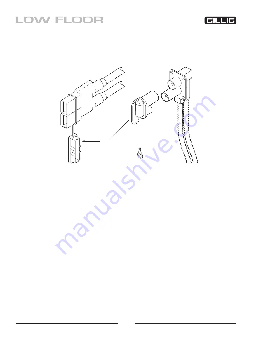
If the bus is equipped with a rear jump start connector, it is located inside the right side engine access
door on the outrigger or behind the utility door above the right tail light. The front jump start connector
may be located behind the battery box door at the front of the vehicle or behind an access door above the
front bumper.
Jump Start Procedure
1. Be sure the jumper cables and connector do not have loose or missing insulation.
2. Check the battery fluid level. If low, fill to the proper level with distilled water.
(See “Electrolyte Maintenance.”)
Replace all caps before jump starting.
3. The booster battery must be of the same voltage as the discharged battery and must have a nega-
tive ground.
4. Do not route the cable on or near pulleys, fans, or other parts which will move when the engine
starts.
5. Set the parking brake and place the transmission in neutral. Turn off all lights, accessories, and
other electrical loads in the vehicle to be started.
6. Do not permit the vehicles to touch each other as this could cause a ground connection which
could cause sparks.
7. If the assisting vehicle is so equipped, plug the jumper cable into its jump start connector. If the
assisting vehicle has no jump start connector, clamp one end of the red (+) jumper cable to the
positive (+) terminal of the booster battery and clamp the black (–) cable to the negative (–) ter
-
minal of the booster battery.
Figure 9-4, Typical Jump Start connectors
Cap
Summary of Contents for LOW FLOOR
Page 18: ...Specifications 18...
Page 58: ...Preventive Maintenance 58...
Page 110: ...Engine 110...
Page 138: ...Transmission Driveline Rear Axle 138...
Page 182: ...Suspension 182...
Page 260: ...Air System 260...
Page 420: ...Electrical System 420 Deutsch DT Series Connectors...
Page 421: ...Electrical System 421...
Page 422: ...Electrical System 422 Deutsch HD 10 Series Connectors...
Page 423: ...Electrical System 423...
Page 424: ...Electrical System 424 Deutsch HD 30 Series Connectors...
Page 425: ...Electrical System 425...
Page 442: ...Heating Air Conditioning 442...
Page 492: ...Body and Interior 492 Figure 11 33 USSC Seat Assembly...
Page 493: ...Body and Interior 493 Figure 11 34 USSC Seat Suspension Assembly...
Page 495: ...Body and Interior 495 Figure 11 37 Seat Air Connections...


