Electrical System
365
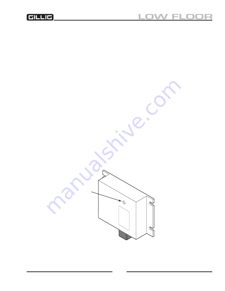
Figure 9-11, Regulator Adjustment
Routine Maintenance
Since there are no brushes or slip rings, the alternator requires only routine, periodic maintenance.
1. Check the alternator mounting bolts and tighten as necessary.
2. Check all the electrical connections for tightness and corrosion. Clean off the corrosion and
tighten connections to torques specified in the
Electrical Schematics Manual
. Be sure the wiring
insulation is in good condition and that all wiring is securely clipped to prevent chafing of the
insulation.
3. With the engine running, listen for noise and check the alternator for vibration. If it is noisy or
vibrating excessively, it should be removed for further inspection or repair.
4. Check the batteries to be sure the terminals are clean and the clamps are tight. Check to ensure
the batteries are not bulging.
On-Vehicle Voltage Adjustment
Check or adjust the voltage regulator setting as follows:
1. Connect a voltmeter across the positive output terminal of the alternator and the regulator case
(negative).
2. Start the engine and operate it at approximately 1,000 rpm (about 2,300 alternator rpm) with
some accessories turned on to obtain a load. Note the voltage setting. A steady reading of
28 +/– 0.2 volts should appear. (This reading may vary depending upon battery type and origi
-
nal customer specifications.) If this reading is not observed, remove the plug from the regulator
cover and turn the adjusting screw inside the regulator to adjust the voltage (Figure 9-11).
3. If the voltage cannot be adjusted by turning the potentiometer, check the alternator as explained
later in this section. If the alternator is found to be satisfactory, replace the regulator.
Adjust Here
Summary of Contents for LOW FLOOR
Page 18: ...Specifications 18...
Page 58: ...Preventive Maintenance 58...
Page 110: ...Engine 110...
Page 138: ...Transmission Driveline Rear Axle 138...
Page 182: ...Suspension 182...
Page 260: ...Air System 260...
Page 420: ...Electrical System 420 Deutsch DT Series Connectors...
Page 421: ...Electrical System 421...
Page 422: ...Electrical System 422 Deutsch HD 10 Series Connectors...
Page 423: ...Electrical System 423...
Page 424: ...Electrical System 424 Deutsch HD 30 Series Connectors...
Page 425: ...Electrical System 425...
Page 442: ...Heating Air Conditioning 442...
Page 492: ...Body and Interior 492 Figure 11 33 USSC Seat Assembly...
Page 493: ...Body and Interior 493 Figure 11 34 USSC Seat Suspension Assembly...
Page 495: ...Body and Interior 495 Figure 11 37 Seat Air Connections...


