Electrical System
370
Alternator Installation
1. Position alternator on mounting bracket.
2. Install washers on the mounting bolts and tighten front (drive end) to 65–75 lb-ft (88–102 N-m)
and rear to 55–65 lb-ft (75–88 N-m) torque.
3.
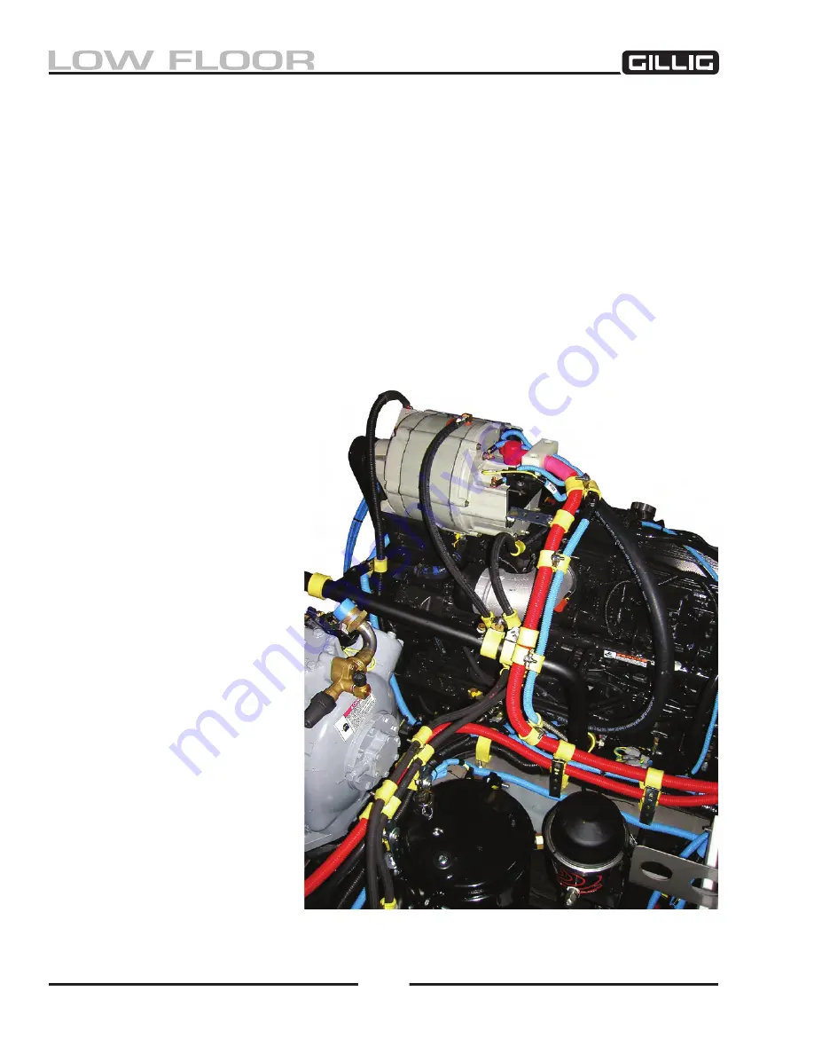
To prevent chaffing, heat damage, engine fire, etc., all cables and hoses should be routed
and clamped in the same way they were before the alternator was removed.
If you took a
picture of cable and hose routing before removing the alternator, refer to it now. Also refer to
“Alternator Cable/Fuse Installation Procedure” on the following two pages.
4. Connect the oil supply line to the alternator. Secure the oil line in the clip attached to the alterna
-
tor drive end frame. When replacing or connecting the oil line, be sure to prevent foreign matter
from entering the oil line or fittings.
5. Connect the wires to the field “F1” (+), field “F2” (–), “RELAY,” and “POS” terminals on the al
-
ternator. Tighten the terminal nuts to torque specified in the
Electrical Schematics Manual
. Hold
bottom nuts.
6. Ensure that the diode end
cover drain plug is securely
tightened.
7. Install the drive belt. See the
engine manual for instruc-
tions.
8. Place the battery disconnect
switches to the “ON” posi
-
tion and place the “Igni
-
tion” and “Start Selector”
switches in the rear run box
in the “ON” and “FRONT”
positions.
9. Run the engine to fill the
diode end with oil, then
check the engine oil level
and replenish as necessary.
Figure 9-14, Example of Cable and Hose Routing
Summary of Contents for LOW FLOOR
Page 18: ...Specifications 18...
Page 58: ...Preventive Maintenance 58...
Page 110: ...Engine 110...
Page 138: ...Transmission Driveline Rear Axle 138...
Page 182: ...Suspension 182...
Page 260: ...Air System 260...
Page 420: ...Electrical System 420 Deutsch DT Series Connectors...
Page 421: ...Electrical System 421...
Page 422: ...Electrical System 422 Deutsch HD 10 Series Connectors...
Page 423: ...Electrical System 423...
Page 424: ...Electrical System 424 Deutsch HD 30 Series Connectors...
Page 425: ...Electrical System 425...
Page 442: ...Heating Air Conditioning 442...
Page 492: ...Body and Interior 492 Figure 11 33 USSC Seat Assembly...
Page 493: ...Body and Interior 493 Figure 11 34 USSC Seat Suspension Assembly...
Page 495: ...Body and Interior 495 Figure 11 37 Seat Air Connections...


