Electrical System
38
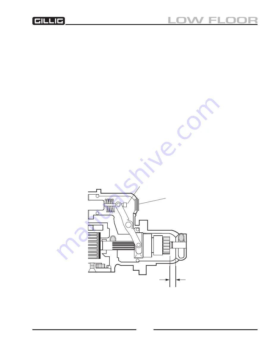
Figure 9-21, Pinion Clearance Adjustment
Pinion Clearance Adjustment
This check must be made with the starter removed from the engine. It is rare that the pinion has to be
adjusted, however if the wear pattern on the pinion teeth indicates that the pinion is not engaging the
flywheel ring gear at the proper position, proceed as follows:
1. Disconnect the field coil connector from the solenoid motor terminal and field frame on the
starter to prevent the starter from turning.
2. Connect a test lead from the positive (+) terminal of a 24 volt battery to the solenoid switch (“S”)
terminal. Connect another test lead from the battery negative (–) terminal to ground on the starter
or solenoid frame.
3.
Momentarily
flash a jumper lead from the solenoid motor terminal to the solenoid frame or
ground terminal. The drive will now shift into the cranking position and remain so until the bat-
tery is disconnected.
Jumping for more than a few seconds will damage the solenoid.
4. Push the pinion back towards the commutator end to eliminate slack movement.
5. Measure the distance between the drive and the housing. The distance should be between 0.330"
and 0.390" (9.3 to 9.7 mm). See Figure 9-
21.
6. To adjust the clearance to the proper amount, remove the plug and adjust the nut on the solenoid
plunger rod as necessary to obtain the proper clearance. After the correct clearance is obtained,
install the access plug and gasket in the shift lever housing.
Incorrect pinion clearance adjust-
ment can cause the solenoid contacts to close with the pinion outside the ring gear and lead
to pinion and ring gear damage.
Pinion
Clearance
Adjustment
20-800-59
0.33 to 0.39 inch
Plug
Summary of Contents for LOW FLOOR
Page 18: ...Specifications 18...
Page 58: ...Preventive Maintenance 58...
Page 110: ...Engine 110...
Page 138: ...Transmission Driveline Rear Axle 138...
Page 182: ...Suspension 182...
Page 260: ...Air System 260...
Page 420: ...Electrical System 420 Deutsch DT Series Connectors...
Page 421: ...Electrical System 421...
Page 422: ...Electrical System 422 Deutsch HD 10 Series Connectors...
Page 423: ...Electrical System 423...
Page 424: ...Electrical System 424 Deutsch HD 30 Series Connectors...
Page 425: ...Electrical System 425...
Page 442: ...Heating Air Conditioning 442...
Page 492: ...Body and Interior 492 Figure 11 33 USSC Seat Assembly...
Page 493: ...Body and Interior 493 Figure 11 34 USSC Seat Suspension Assembly...
Page 495: ...Body and Interior 495 Figure 11 37 Seat Air Connections...


