Electrical System
390
Timed Action
This symbol, which looks like a box interrupting a horizontal line (see Figure 9-37), indicates that the
timed function listed inside the box will affect whatever action is listed to the right of the box on the
ladder chart. In some cases, there may be a delay before an action is taken; in others, an action may be
taken for a specified amount of time, then stopped. In the example here, the DOOR ALARM output
B1-22 will be activated for three seconds, then turned off.
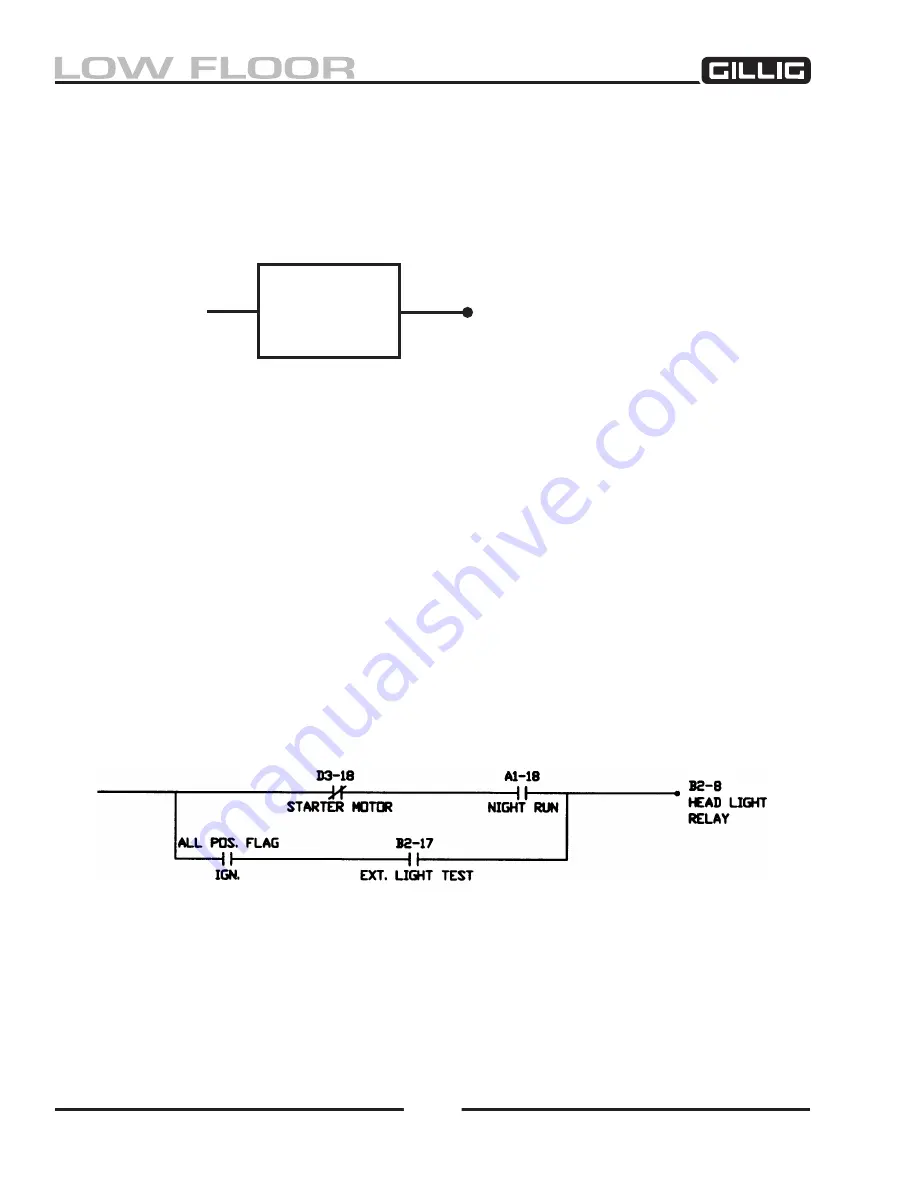
Figure 9-38, Headlight Relay Ladder Chart
Figure 9-37, Timed Action Taken
TURN ON
3 SEC
B-22
DOOR
ALARM
Reading the Ladder Charts
Refer to Figure 9-38
. Each circuit shown on the ladder charts starts with a single line on the left and ends
with a single output on the right. The multiplexer system checks for the required conditions, scanning
from left to right. If a path can be completed (by meeting all the required conditions between the start
of the circuit on the left and the output on the right), power is sent to the output. In most cases, there is
more than one path that will activate the output; in these circuits, any completed path will activate the
output. For example, in Figure 9-38
, there are two ways to send power to the HEAD LIGHT RELAY at
B2-8. One way is for all the conditions on the upper path to be met; for this to happen, the STARTER
MOTOR input at D3-18 must be OFF and the NIGHT RUN input at A1-18 must be ON.
Both
(or
all
,
if there are more than two conditions) of those conditions must be met before the upper path can be
completed and power sent to the headlights. Another way to send power to the HEADLIGHT RELAY
output is to complete the lower path, shown in Figure 9-38
. To do this, the ALL POS. FLAG and EXT.
LIGHT TEST inputs must
both
be ON.
Summary of Contents for LOW FLOOR
Page 18: ...Specifications 18...
Page 58: ...Preventive Maintenance 58...
Page 110: ...Engine 110...
Page 138: ...Transmission Driveline Rear Axle 138...
Page 182: ...Suspension 182...
Page 260: ...Air System 260...
Page 420: ...Electrical System 420 Deutsch DT Series Connectors...
Page 421: ...Electrical System 421...
Page 422: ...Electrical System 422 Deutsch HD 10 Series Connectors...
Page 423: ...Electrical System 423...
Page 424: ...Electrical System 424 Deutsch HD 30 Series Connectors...
Page 425: ...Electrical System 425...
Page 442: ...Heating Air Conditioning 442...
Page 492: ...Body and Interior 492 Figure 11 33 USSC Seat Assembly...
Page 493: ...Body and Interior 493 Figure 11 34 USSC Seat Suspension Assembly...
Page 495: ...Body and Interior 495 Figure 11 37 Seat Air Connections...


