40
Electrical System
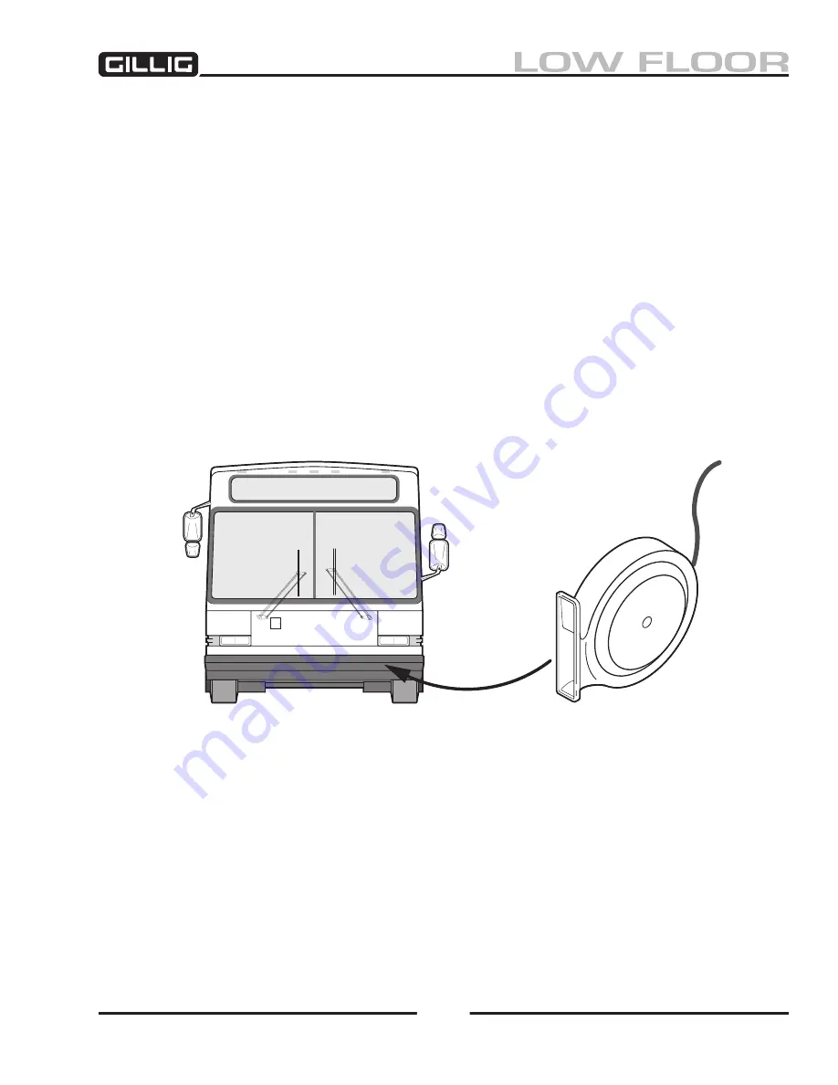
Figure 9-45, Driving Horn
20-800-64
ELECTRIC HORNS
A set of horns, operated by the button in the center of the steering wheel, are mounted in the headlight
channel in the front of the coach (Figure 9-
45
).
These horns are energized through the horn relay with 12 volts supplied by a circuit breaker on the 12
volt battery feed bus bar when the horn button is pressed and held. See the “Horns” wiring diagram in
the
Electrical Schematics Manual
for the circuit and connection affected.
If the horns do not operate, quick checks may be made as follows:
1. Connect a jumper lead from terminal 86 on the horn relay to ground. If the horn operates, the
trouble is in the horn control circuit between the horn button and the horn relay. If the horn does
not operate, proceed with the next step.
2. Momentarily connect a jumper lead between terminal 30 and terminal 87 on the horn relay. If the
horn operates, the relay is defective. If the horn does not operate, proceed to next step.
3. Apply 12 volt power to the horn to test the individual horns.
4. If all the above remedies fail, remove and replace the horn assembly.
Summary of Contents for LOW FLOOR
Page 18: ...Specifications 18...
Page 58: ...Preventive Maintenance 58...
Page 110: ...Engine 110...
Page 138: ...Transmission Driveline Rear Axle 138...
Page 182: ...Suspension 182...
Page 260: ...Air System 260...
Page 420: ...Electrical System 420 Deutsch DT Series Connectors...
Page 421: ...Electrical System 421...
Page 422: ...Electrical System 422 Deutsch HD 10 Series Connectors...
Page 423: ...Electrical System 423...
Page 424: ...Electrical System 424 Deutsch HD 30 Series Connectors...
Page 425: ...Electrical System 425...
Page 442: ...Heating Air Conditioning 442...
Page 492: ...Body and Interior 492 Figure 11 33 USSC Seat Assembly...
Page 493: ...Body and Interior 493 Figure 11 34 USSC Seat Suspension Assembly...
Page 495: ...Body and Interior 495 Figure 11 37 Seat Air Connections...


