4
Electrical System
TEST
EXTERIOR
LAMPS TEST
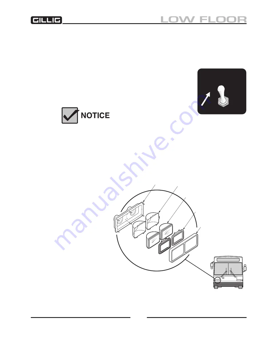
Figure 9-52, Exterior
Lamps Test Switch
ExTERIOR LIGHTING EqUIPMENT
Circuit diagrams for the exterior lights and their controlling switches, relays, and circuit breakers, are
shown on the applicable wiring diagrams in the
Electrical Schematics Manual
.
Exterior Lamps Test Switch
Mounted on the underside of the electrical component compartment (above
the driver’s side window), the Exterior Lamps Test switch uses the multiplex
system to activate every exterior lamp on the bus except for the backup lights.
This test does
not
check the systems which control the lamps, only the lamps
themselves. For example, the turn signal lamps may flash when the Exterior
Lamps Test switch is activated even if the turn signal switches are bad.
The Exterior Lamps Test Switch tests the condition of
the bulbs and wiring only. It does not take the place
of a thorough exterior lighting systems inspection,
with an observer outside the bus checking each lamp
as it is activated.
Headlights
The dual headlight assembly (Figure 9-53)
consists of two rectangular sealed beam
lamp units. The outboard lamps are
double filament units which consist of
an upper and lower beam unit. The
inboard lamps are single filament
units which are only used when the
outboard units are in the high beam
mode of operation. The outboard
units are identified as type 2A and
have “2A” molded into the top
of the lens. The inboard units are
identified as type 1A and have “1A”
molded into the top of the lens.
The sealed beam lens incorporates
aiming bosses into its construction,
which allows adjustment of the lamp
without having to use an aiming
screen or a large work area. Adjust-
ment can be accomplished using
headlight aiming tool J-25300-A, or
20-800-74
HIGH LOW/BEAM (2A)
RETAINER
TRIM
MOUNT
BACKING
Figure 9-53, Headlights
Summary of Contents for LOW FLOOR
Page 18: ...Specifications 18...
Page 58: ...Preventive Maintenance 58...
Page 110: ...Engine 110...
Page 138: ...Transmission Driveline Rear Axle 138...
Page 182: ...Suspension 182...
Page 260: ...Air System 260...
Page 420: ...Electrical System 420 Deutsch DT Series Connectors...
Page 421: ...Electrical System 421...
Page 422: ...Electrical System 422 Deutsch HD 10 Series Connectors...
Page 423: ...Electrical System 423...
Page 424: ...Electrical System 424 Deutsch HD 30 Series Connectors...
Page 425: ...Electrical System 425...
Page 442: ...Heating Air Conditioning 442...
Page 492: ...Body and Interior 492 Figure 11 33 USSC Seat Assembly...
Page 493: ...Body and Interior 493 Figure 11 34 USSC Seat Suspension Assembly...
Page 495: ...Body and Interior 495 Figure 11 37 Seat Air Connections...


