Body and Interior
474
Rear Door Microswitch Adjustment
Adjustments should be performed in the following sequence (
Note: The LS2 and LS3 microswitches are
typically present only on buses equipped with touchbar-actuated rear doors. Your bus may not have the
LS2 and LS3 switches)
:
1. LS1 Switch adjustment
Connecting rod adjustment
2. Unlock solenoid adjustment
Emergency release
3. LS2 Switch adjustment
4. LS3 Switch adjustment
Door stops
Cylinder rod adjustment
5. Touchbars
6. Door speed adjustments
7. Check components and hardware
8. Check wiring
Rear Door Adjustment Procedures
LS Adjustment
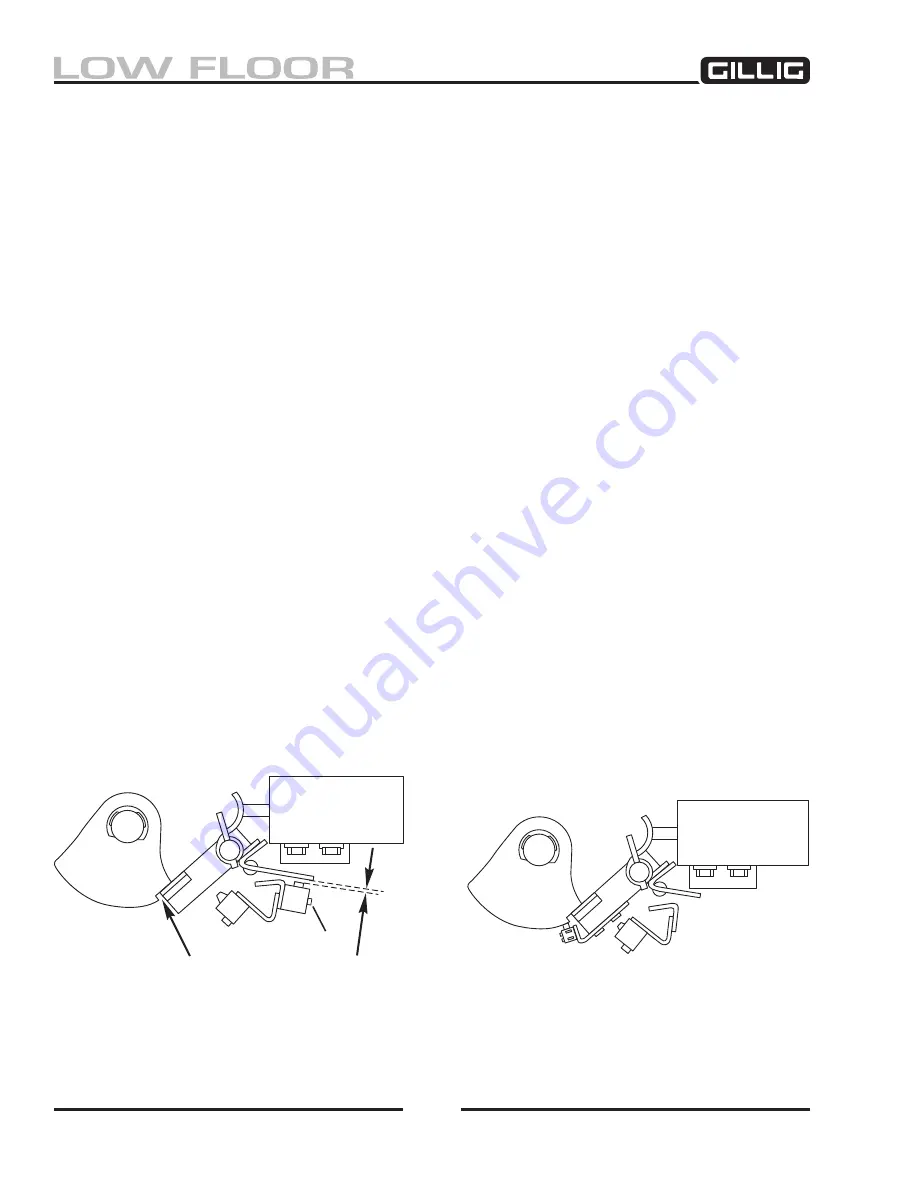
The LS1 Switch is used to activate the brake interlock circuit. This switch has two separate circuits, one
which is normally open and another which is normally closed; one or both of the switch circuits will be
used depending on the options installed on your bus. Refer to the Gillig
Electrical Schematics Manual
for your bus for specific information on the LS1 switch circuits. The LS1 switch MUST be activated
with the doors locked (while the lock pawl is engaged in the cam notch). The LS1 switch plunger MUST
NOT bottom out. If the LS1 switch is mounted directly on the lock pawl, no adjustment is needed. See
Figure 11-23.
Figure 11-23, LS1 Switch Adjustment
1/16" miN - 1/8" mAX
0.016" feeler gAuge wheN
ls1 pluNger is bottomed
cAm
soleNoid
locK pAwl
ls2
ls1
AdJustiNg screw
NOTE: ADJUST CONN RODS
with doors closed to
obtAiN this dimeNsioN
NOTE: LS1 SWITCH MUST AC
-
tivAte wheN locK pAwl is
eNgAged iN Notch cAm
cAm
soleNoid
locK pAwl
ls2
ls1
this ls1 coNfigurAtioN
reQuires No AdJustmeNt
Summary of Contents for LOW FLOOR
Page 18: ...Specifications 18...
Page 58: ...Preventive Maintenance 58...
Page 110: ...Engine 110...
Page 138: ...Transmission Driveline Rear Axle 138...
Page 182: ...Suspension 182...
Page 260: ...Air System 260...
Page 420: ...Electrical System 420 Deutsch DT Series Connectors...
Page 421: ...Electrical System 421...
Page 422: ...Electrical System 422 Deutsch HD 10 Series Connectors...
Page 423: ...Electrical System 423...
Page 424: ...Electrical System 424 Deutsch HD 30 Series Connectors...
Page 425: ...Electrical System 425...
Page 442: ...Heating Air Conditioning 442...
Page 492: ...Body and Interior 492 Figure 11 33 USSC Seat Assembly...
Page 493: ...Body and Interior 493 Figure 11 34 USSC Seat Suspension Assembly...
Page 495: ...Body and Interior 495 Figure 11 37 Seat Air Connections...


